PLEASE READ FIRST
Congratulations on your purchase of the TrolMaster HCS-1 Hydro-X Control System. This unit is an efficient and
affordable way to fully control your grow rooms. To ensure safety, please read this instruction manual carefully
before installation and follow the instructions herein. It will provide detailed instructions and guidelines that
will help to set up the unit, and to understand the full capability of this unit. Any use or application of this
product, other than for its original intended purposes are prohibited. Store this manual in a secure place for
future reference.
INTRODUCTION
Hydro-X Control System is the most intelligent and versatile environmental control system on the market. It could
control up to 512 lights, 4 temperature devices, 2 humidity devices, 2 CO2 devices, 9 preprogram devices. With the
incredible flexibility, anyone could easily customize their own grow room system for maximum yield.
The system comes with a 3-in-1 sensor detecting temperature, humidity & light. A CO2 sensor is available for
measuring CO2 level. When the measured value exceeds your custom setting range, a warning message will be sent to
your smartphone. Smoke detectors are also available for smoke detection to alert you if there is a fire. Hydro-X
helps you to monitor your grow environments perfectly.
Hydro-X is specially designed to set up a daily lighting management for your lighting system. Having 2 separate
lines allows the user to create multiple lighting layouts (and dimming sequence) based on their individual
preferences. This system can efficiently control your lighting system by running a schedule with advanced functions
like auto dimming, overheat shutdown, sunrise & sunset simulation.
Hydro-X can control almost all kinds of devices in your grow rooms by its 4 types of device stations. Temperature
device stations, humidity device stations, CO2 device stations and program device stations are designed to be
connected to different devices for centralized control. Hydro-X offers a more smart and flexible approach for the
connection of the devices you want to be controlled.
Hydro-X keeps pace with the times, it has the ability to connect to the network directly with a standard network
cable. After downloading the app, you can monitor and control the environment of your grow rooms anytime and
anywhere. You could read the historical data by graph on your smartphone and receive warning messages if the
growing
environment exceeds your setpoints. A micro-SD card is also available for data logging if the Internet is
unavailable. With Hydro-X, you can monitor and control the growing environment at your fingertips.
FACTS
Here are some important things to consider when using the Hydro-X Control System.
COMPONENTS
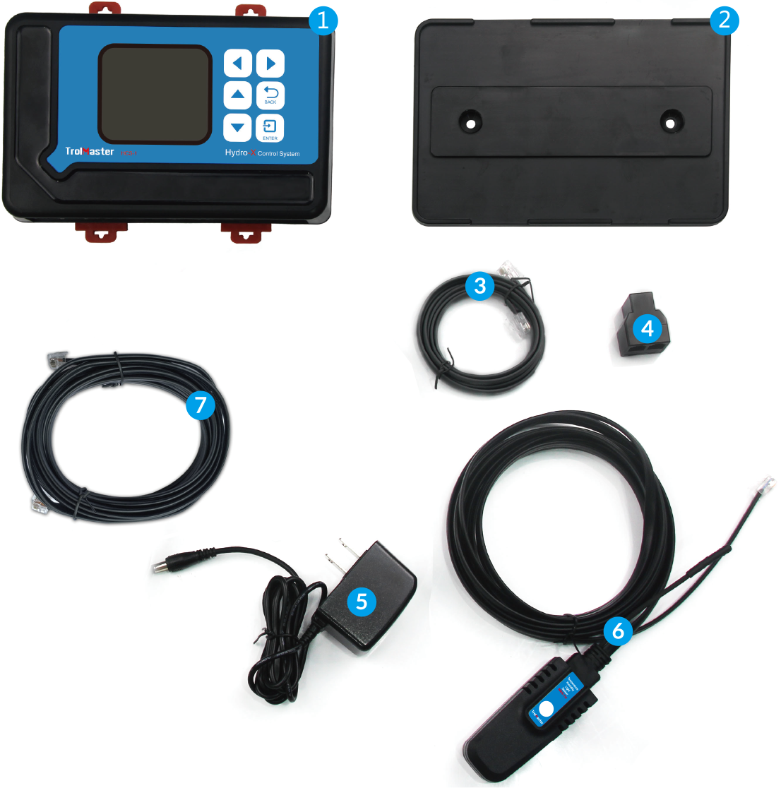
1. Controller
2. Back Plate(Bracket)
3. 4ft RJ12 Cable
4. T-Shape Splitter
5. 12DC Power Supply
6. 3-in-1 Sensor
7. 16ft RJ12 Cable
INSTALLATION
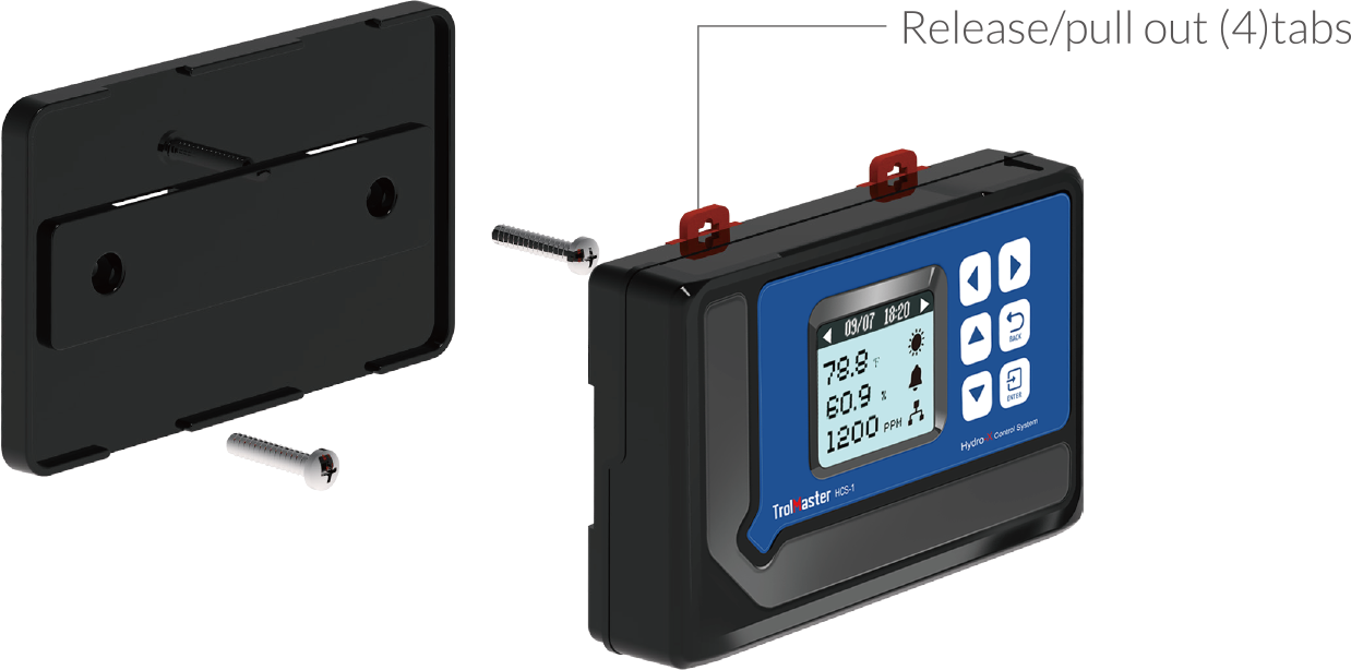
Determine where to locate the main controller. The controller comes with a simple to use DIN type bracket. Pull the
4 tabs outward to release the bracket from the unit, mount the bracket to a wall or surface, place the unit back on
the bracket and press the 4 tabs back in to lock the unit in place. The interconnecting RJ12 communication cables
are available in different lengths, select the correct length for your application. The HCS-1 Hydro-X Control
System is supplied with a 4ft and 16ft cable. These interconnecting RJ12 cables are also available in lengths of
25ft and 50ft. Select the correct length for your application.
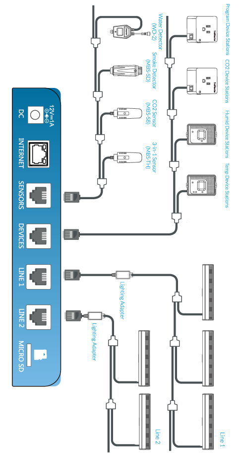
CONNECTIONS
CONNECTIONS CONTINUED...
1. Power Connection:Connect the plug-in power supply to
the power (DC) connector.
2. Sensor connection:Connect the RJ12 cable to the
SENSORS connector and connect to a splitter on the other end. Plug the 3-in-1 sensor to the splitter for
connection. The other connector on the splitter can be used to continuously connect to the next splitter. Connect a
CO2 sensor to the 2nd splitter. Repeat the procedure and connect one or more smoke detector(s) if needed. Press the
small button on the smoke detector, the Hydro-X automatically assign an address to the unit sequentially.
3. Device Station Connection (main controller needs to be powered on)Connect
the cable going from the DEVICES connector to the first Device Station to be connected. Use the T-shape splitter
and short RJ cable so that the first cable can continue on to be connected to the next T-shape splitter (Device
Station) to be connected. Plug the Device Station to the wall outlet for power supply. Press the small button on
the device station, the system will automatically assign an address to the device station in sequence. Repeat this
process until all device stations are connected to the main controller.
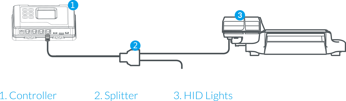
4. Light Connectiona ) For HID LightsConnect the
cable going from LINE 1 to the rst digital ballast to be connected. Use the T-shape splitter and short RJ cable so
that the first cable can continue on to be connected to the next T-shape splitter (ballast) to be connected.Repeat
this process until all ballasts (fixtures) are connected to the LINE 1. Connect more lights through the LINE 2
port. Same procedures applied for LINE 1.
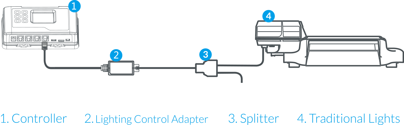
b) For Traditional Lights
If connected to traditional lights which are controlled by analog (0-10v) such as Gavita fixtures, a lighting
control adapter (signal converter) is necessary to convert the digital signal into analog signal. The connection is
similar as above but with a signed converter connected between ballast and controller. First, connect the signal
converter to the LINE 1 or LINE 2 connector and then connect to a splitter on the other end. Finally, use another
RJ12 cable to connect between the splitter and the analog ballast. See the connection diagram.
Each line can be set up to be a "staged" dimming zone. In other words, each zone has its own independent dimming
temperature setting as well as the dimming actiaon. Having 2 lines allows the user to create multiple lighting
layouts (and dimming sequences) based on their individual preferences. Some examples are shown below.

5. Internet Connection
This unit has the feature of connecting the network for remote control.User can use a standard network cabale for
connection thruogh the INTERNET connector
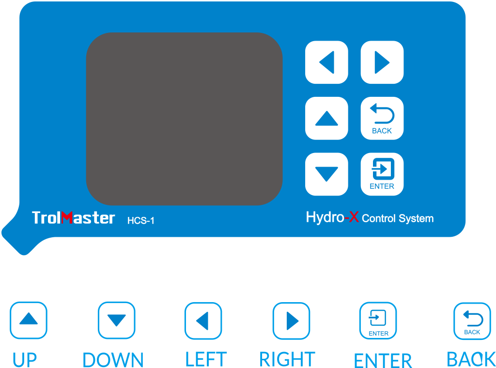
BUTTONS
The HCS-1 Hydro-X Control System is extremely easy to use. The backlit 128x128 LCD display will provide the user
with the current conditions and access all settings.All settings are accessed by using the 6 pushbuttons on the
front of the unit. The button functions are described below.
UP / DOWN : The Up and Down buttons move the cursor up and down to select the
item on the LCD display.
LEFT / RIGHT : The Left and Right buttons move the cursor to previous page or
next page, left item or right item.
BACK : The Back button goes backwards to the previous page.
ENTER : The Enter button is used to open the menu item to be changed as well
as to accept and save the new setting.
Familiarize yourself with the function of the 6 buttons on the front of the HCS-1 Hydro-X Control System in order
to able to access settings, and to better understand how to use the HCS-1 Hydro-X Control System to its greatest
potential.
START SETTINGS
Once you have connected all devices, sensors and fixtures to the HCS-1 Hydro-X Control System, we can start
using the unit.
Connect the plug-in power supply to the power connector on the bottom of theHCS-1 Hydro-X Control System. HCS-1
Hydro-X Control System will turn on and boot up.
If it is the first time you have used the HCS-1 Hydro-X Control System, when you power on the HCS-1 Hydro-X Control
System, the Welcome screen / page will be displayed.
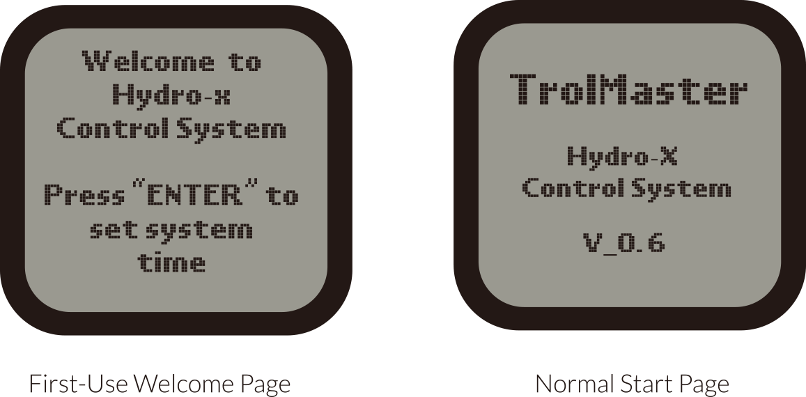
*NOTE : Press ENTER button to rst go to the Conguration page
and begin set-up.
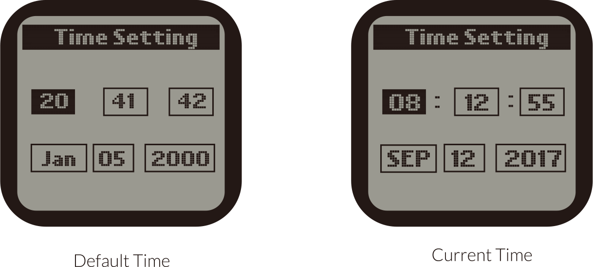
Time Setting : please refer to P25 for the time setting so as to change the
default time into the current time before use.
MAIN MENU
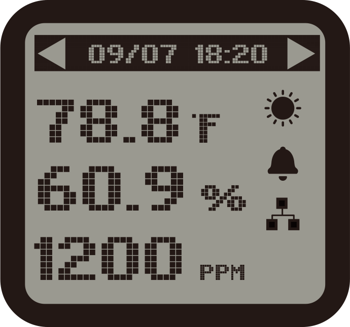
1 ). The main menu displays three elements:
Temperature Value (��F) eg: 78.8��F
Humidity Value (%) eg: 20.2%
CO2 Level (PPM) eg: 1200 PPM
The top title bar indicates current date & time:
Month/Date eg: 09/07
Hour/Minute eg:18:20
Day Mode

Night Mode

Alarm Activated

Internect Connected

No Network Connection (no icon)
NOTE : Download the TrolMaster app from App Store or Google Play
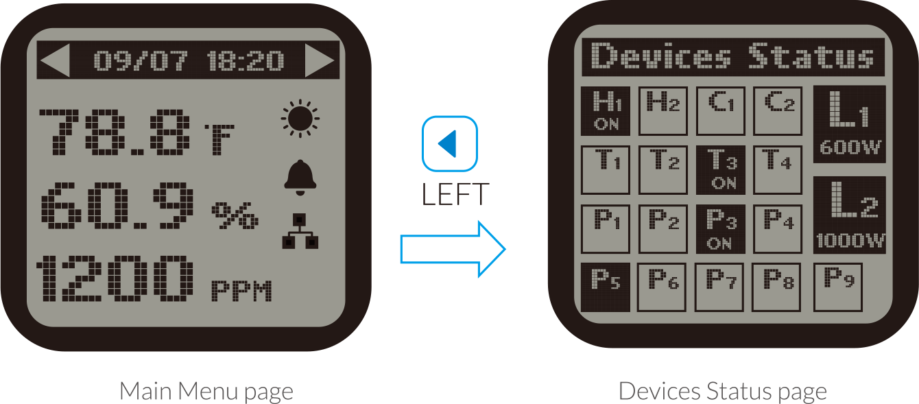
2 ). On the Main Menu page, press LEFT button  to get access to Devices Status page. The screen will show
devices in 3 states .
a ). State One :
to get access to Devices Status page. The screen will show
devices in 3 states .
a ). State One :  Highlighted and with "ON" indicates the device is connected and under working condition (activated).
b ). State Two :
Highlighted and with "ON" indicates the device is connected and under working condition (activated).
b ). State Two :  Highlighted and without "ON" indicates the device is connected but not under working condition (standby)
c ). StateThree :
Highlighted and without "ON" indicates the device is connected but not under working condition (standby)
c ). StateThree :  Non-highlighted indicates no device station connected to this address.
to get access to Devices Status page. The screen will show
devices in 3 states .
a ). State One :
Highlighted and with "ON" indicates the device is connected and under working condition (activated).
b ). State Two :
Highlighted and without "ON" indicates the device is connected but not under working condition (standby)
c ). StateThree :
Non-highlighted indicates no device station connected to this address.
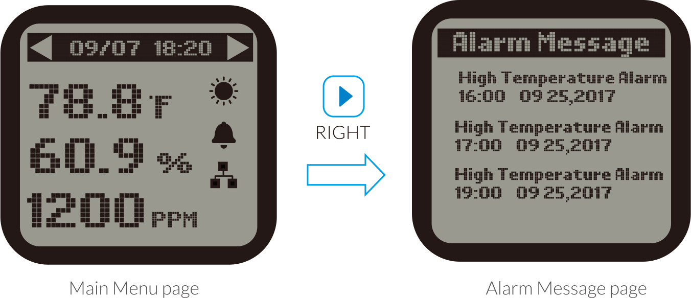
3 ). On the Main Menu page, press RIGHT button  to get access to Alarm Message page. The LCD screen will show records of all alarm messages.
to get access to Alarm Message page. The LCD screen will show records of all alarm messages.
*NOTE :
a ). On the Devices Status page, the device states are not suitable to lighting devices.The LCD screen will display
the lighting status for two lighting lines L1 & L2.
b ). Do not remove the Micro-SD card in the main screen (showing Temperature, Humidity & CO2 ).Otherwise, it is
easy
to cause damage to the card.
SETTING PAGE
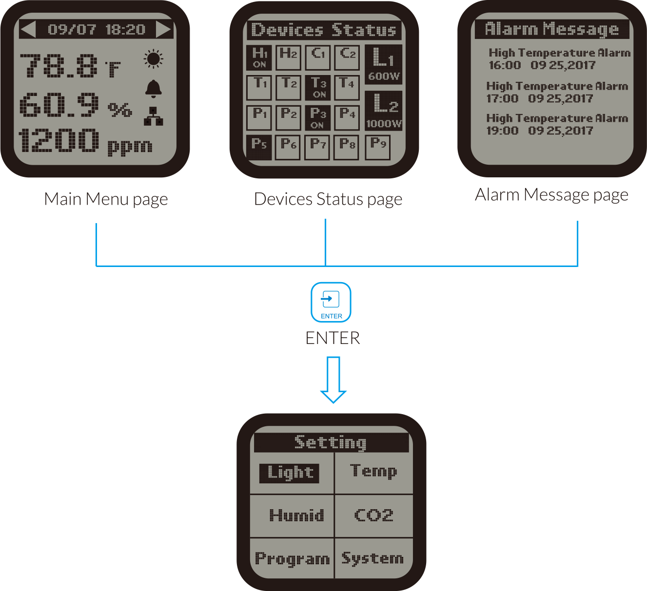
On the Main Menu page, Device Status page or Alarm Message page, press ENTER button  to get access to the SETTING page. The LCD screen will display 6
subjects ( Light / Temp / Humid / CO2 / Program / System) as shown on the picture. You can move the cursor (UP /
DOWN / LEFT / RIGHT) to select each subject you want to make setting.
to get access to the SETTING page. The LCD screen will display 6
subjects ( Light / Temp / Humid / CO2 / Program / System) as shown on the picture. You can move the cursor (UP /
DOWN / LEFT / RIGHT) to select each subject you want to make setting.
to get access to the SETTING page. The LCD screen will display 6
subjects ( Light / Temp / Humid / CO2 / Program / System) as shown on the picture. You can move the cursor (UP /
DOWN / LEFT / RIGHT) to select each subject you want to make setting.
LIGHTING SETTINGS
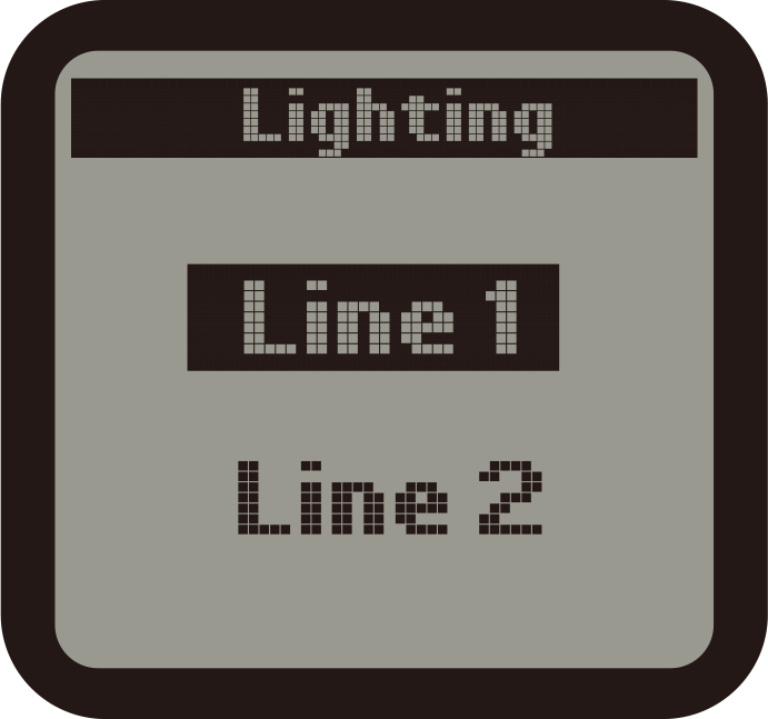
On the Setting page, select the Light subject and then press ENTER button
to confirm your selection. The screen will display Line 1 and Line 2. Press UP button  or DOWN button
  to select Line 1 or Line 2. Then press ENTER button
to get into the configuration page.
to select Line 1 or Line 2. Then press ENTER button
to get into the configuration page.
to confirm your selection. The screen will display Line 1 and Line 2. Press UP button or DOWN button
to select Line 1 or Line 2. Then press ENTER button
to get into the configuration page.
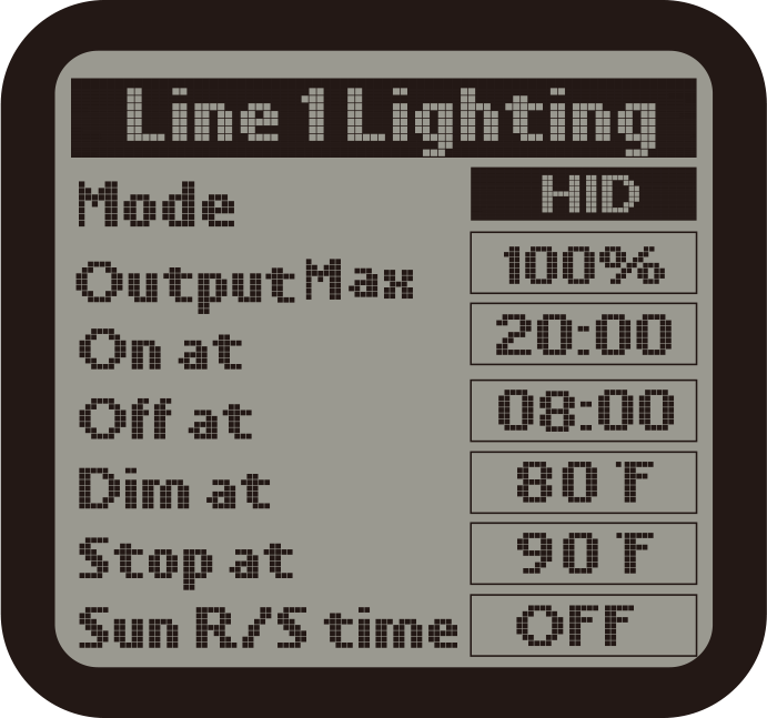
2 ) Use the UP and Down button to select the optional item. Press ENTER button, the digits will be flashing, then
press
UP or DOWN button for change. Finally, press ENTER button to confirm and save change.
Wattage : Select the wattage of ballast that will be connected to this line.
Output Max : Select the wattage that you would like to operate the fixtures in
increment of 25 watts. User can
select any setting between 600 watts and 1150 watts for the 1000 watt fixture.
On at : The time of day that the lights for that LINE 1 will be turned ON.
Off at : The time of day that the lights for that LINE 1 will be turned OFF.
Dim at : Select the temperature you want the lights within each line to dim.
Stop at : The max temperature that the growing area can get to before shutting
down the lights. Normally, set at
least 5oF up to 10 degrees F above the "Dim at" setting.
Sun R/S time : simulate Sunrise and Sunset by slowly raising and lowering the
lighting level ( brightness). User can
select from 0 minite(off) to 30 minutes in 5-minute increments for the Sunrise / Sunset feature.
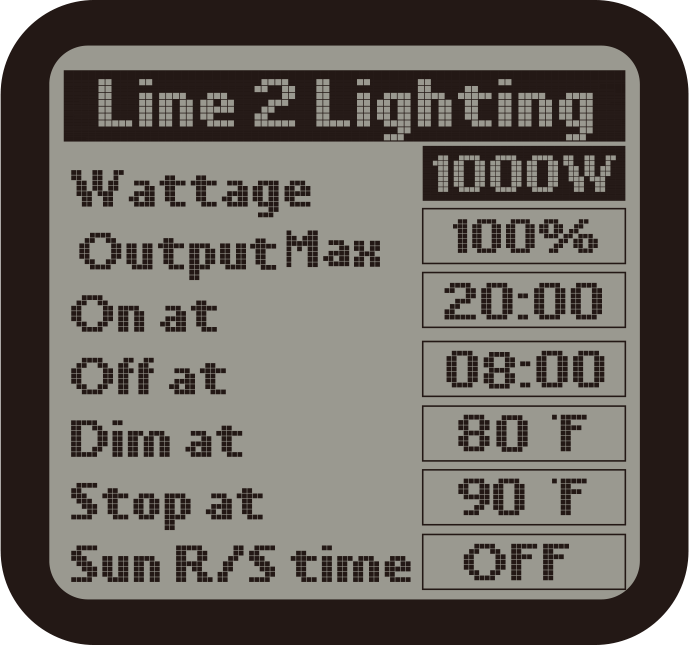
3 ) The lighiting configurations of Line 2 is same as the setting of Line 1.
TEMPERATURE SETTINGS
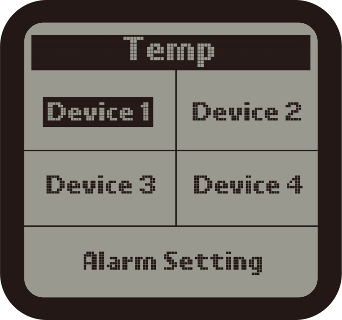
1 ) On the Setting page, select the Temp subject and then press ENTER button
to access the Temp setting page. Use the Up button
or DOWN button to select the device or
Alarm Setting.
to access the Temp setting page. Use the Up button
or DOWN button to select the device or
Alarm Setting.
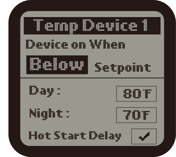
2 ) When the Device 1 is selected, user can set the temperatuesetpoint for Day / Night mode for the Device 1. The
unit
will automatically turn ON the Temp Device 1 when the measured temperature is ABOVE or BELOW the setpoint. Press
ENTER button and the Above or Below text will be flashing. Press UP or DOWN button to change between Above and
Below. Finally, press ENTER button to confirm and save the change.
For example : Turn on device when temp Above setpoint for Cooling
devices; Turn
on device when temp Below setpoint for Heating devices.
Use UP and DOWN button to select Day mode or Night mode, the selected item will be highlighted. Press ENTER button
and the current temperature value will be flashing. Press UP or DOWN button to change the setpoint. Finally, press
ENTER button to confirm and save the change. The LCD will display " Setting saved ".
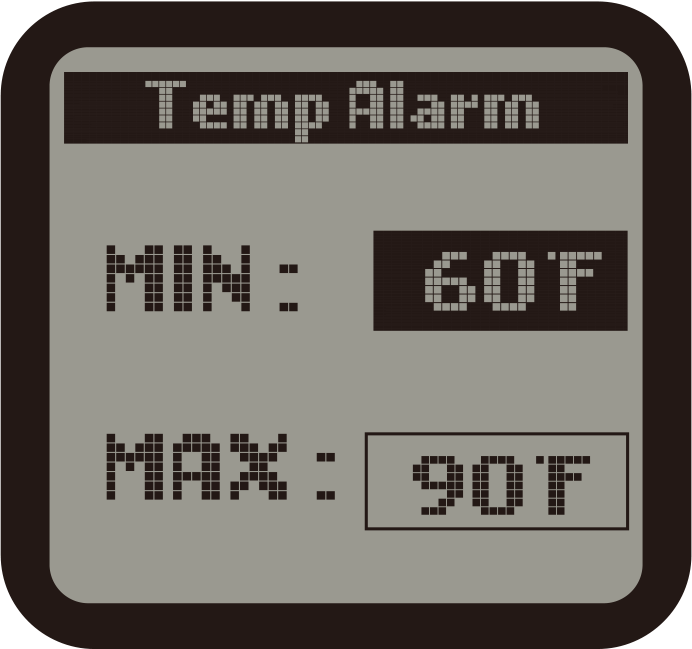
3 ). Press DOWN button to select and enter the Temp Alarm page. The screen will display the Min/Max setpoint. Press
UP or DOWN button to select the Min or Max setpoint. The selected item will be highlighted. Then press ENTER button
again, the current temperature setpoint will be flashing. Press UP or DOWN button to change the setpoint. Finally,
press ENTER button to confirm and save the change. The LCD will display "Setting saved".
When the Temperature level exceeds the setting range, the unit will send a warning message to your smartphone
The setting procedure of other Temp Device Station is same as above
HUMIDITY SETTINGS
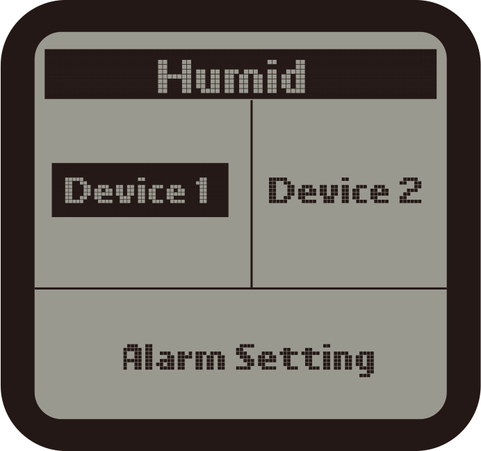
1 ). On the Setting page, select the Humid subject and then press ENTER button
to access the Humid setting page. Use the Up button
or Down button to select the Device 1
or Device 2 or Alarm Setting.
to access the Humid setting page. Use the Up button
or Down button to select the Device 1
or Device 2 or Alarm Setting.
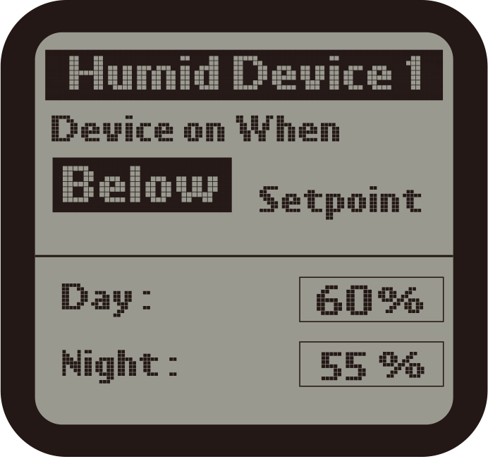
2 ). When the Device 1 is selected, user can set the humidity setpoint for Day / Night mode for the Device 1. The
unit will automatically turn ON the Humid Device 1 when the measured humidity is ABOVE or BELOW the setpoint. Press
ENTER button and the Above or Below text will be flashing. Press UP or DOWN button to change between Above and
Below. Finally, press ENTER button to confirm and save the change. The LCD screen will display " Setting
saved "
For example : Turn on device when humidity level Above setpoint for Dehumidifier;
Turn on device when humidity level Below setpoint for Humidifier.
Use UP and DOWN button to select Day mode or Night mode, the selected item will be flashing. Press UP or DOWN
button to change the setpoint. Finally, press ENTER button to confirm and save the change. The LCD will display "
Setting saved".
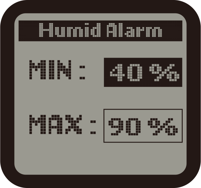
3 ). Press DOWN button to select and enter the Humid Alarm page. The screen will display the Min/Max setpoint.
Press
UP or DOWN button to select the Min or Max setpoint. The selected item will be highlighted. Then press ENTER button
again, the current humidity setpoint will be flashing. Press UP or DOWN button to change teh setpoint. Finally,
press ENTER button to confirm and save the change. The LCD will display "Setting saved".
When the humidity level exceeds the setting range, the unit will send a warning message to your smartphone.
The setting procedure of other Humid Device Station 2 is same as above
CO2 SETTINGS
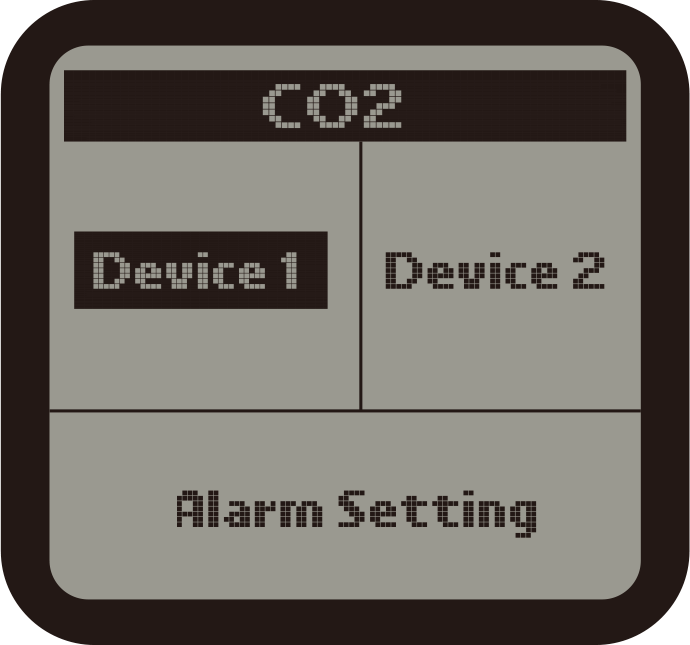
1 ). On the Setting page, select the CO2 subject and then press ENTER button
to access the CO2 setting page. Use the Up button
or Down button to select the Device 1
or Device 2 or Alarm setting.
to access the CO2 setting page. Use the Up button
or Down button to select the Device 1
or Device 2 or Alarm setting.
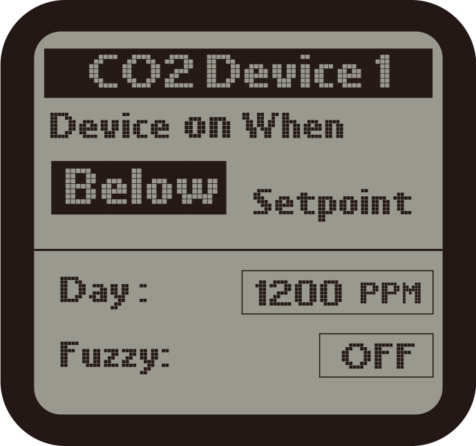
2 ). When the Device 1 is selected, user can set CO2 setpoint during Daytime for the Device 1. The unit will
automatically turn ON the CO2 Device 1 when the measured CO2 level is ABOVE or BELOW the setpoint. Press ENTER
button and the Above or Below text will be flashing. Press UP or DOWN button to change between Above and Below.
Finally, press ENTER button to confirm and save the change. The LCD screen will display "Setting saved"
For example : Turn on device when CO2 level Above setpoint for Exhaust fan; Turn
on device when CO2 level Below
setpoint for CO2 Generator or Regulator.
User can set the setpoint for Day mode. Press DOWN button to select the CO2 value. Press ENTER button and the
current CO2 value will be flashing. Press UP or DOWN to change the CO2 setpoint with the increment of 10. Finally,
press ENTER button to confirm and save the change.
User an also turn ON or OFF the Fuzzy Logic mode. Press DOWN button to select the Fuzzy subject and then press UP
or DOWN button to change between ON and OFF status. Finally, press ENTER button to confirm and save teh change.
NOTE :
1. Fuzzy Logic mode is only for the control of CO2 Regulator. Do not turn on while connectig to a CO2 generator.
2. Fuzzy Logic mode counters rising or falling CO2 levels by quickly activating the CO2 selenoid valve, allowing
CO2 levels to be controlled more precisely.
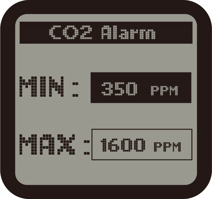
3 ). Press DOWN button to select and enter the CO2 Alarm page. The screen will display the min/max setpoint. Press
UP or DOWN button to select the Min or Max setpoint. The selected item will be highlighted. Then press ENTER button
again, the current CO2 setpoint will be flashing. Press UP or DOWN button to change teh setpoint. Finally, press
ENTER button to confirm and save the change. The LCD will display "Setting saved".
When the CO2 level exceeds the setting range, the unit will send a warning message to your smartphone
The setting procedure of CO2 Device Station 2 is same as above
PROGRAM SETTINGS
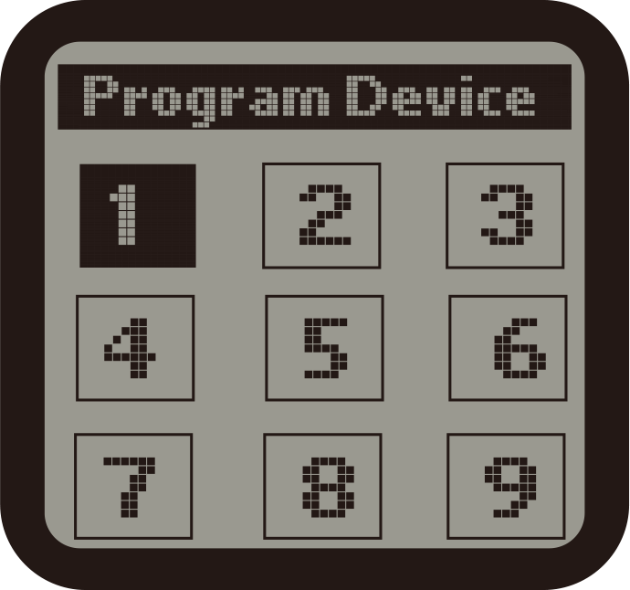
1 ) On the Setting page, select the Program subject and then press ENTER button
to confirm your selection. The screen will display total 9 preset numbers: 1, 2, 3...9. You can assign total 9
additional devices with the preset numbers from program device 1 to program device 9.
to confirm your selection. The screen will display total 9 preset numbers: 1, 2, 3...9. You can assign total 9
additional devices with the preset numbers from program device 1 to program device 9.
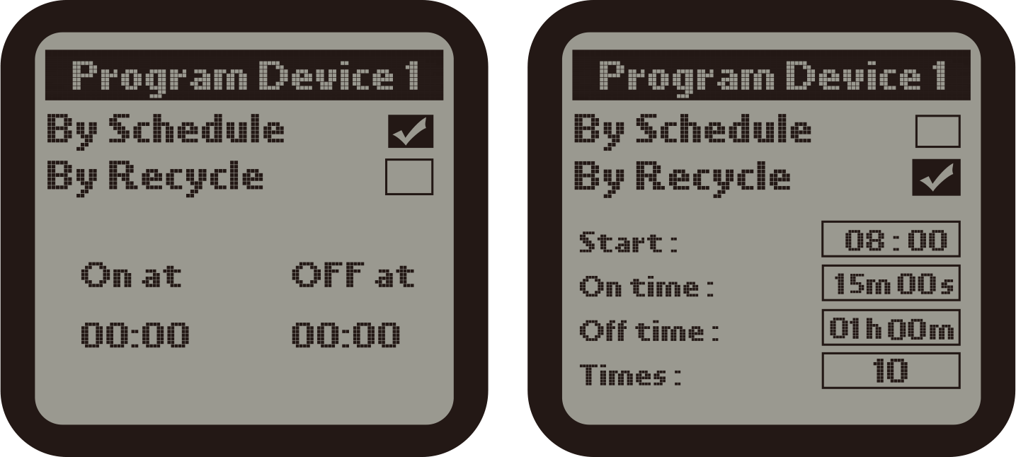
2). Press number 1 to enter into the Program Device 1 page. There are two timing control type: By Schedule & By
Recycle. Press ENTER button, the TICK icon will be highlighted and flashing. Then press UP or DOWN button to select
By Schedule or By Recycle. Finally, press ENTER button to confirm your selection and the LCD will display" setting
saved". Press UP or DOWN button to select the subdirectory you desire to change. The selected item wil be
highlighted, press ENTER button it will be flashing. Press UP or DOWN button to change the time and press ENTER
button to save your change. The number of times ( frequency) starts from 1 to 100.
a ). By Schedule :
On : The start time of continuous working time of the Program Device 1.
Off : The finish time of continuous working time of the Program Device 1.
b ). By Recyle :
Start : The start time of cycle working time of the Program Device 1.
ON Time : The duration of working time per cycle for the Program Device 1.
OFF Time : The duration of non-working time per cycle for the Program Device
1.
Times : The number of times of the daily working cycle.
The setting procedure of other Program Device Station is same as above.
NOTE : if the total cycle time exceeds 24 hours, the maximum
cycle times will be reduced automatically.
SYSTEM SETTINGS
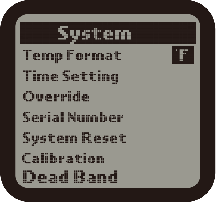
1 ).On the Setting page, select the System subject and then press ENTER button
to confirm your selection . There are 6 subjects:
Temp Format : Select whether to display F or C for temperature measurements.
Time Setting : Enter the time setting page.
Override : Enter the Override page.
Serial Number : Show the device serial number.
System Reset : Enter the system reset page.
Calibration : Enter the temperature humidity and CO2 sensor calibration page.
DeadBand : Enter the temperature humidity and CO2 deadband setting page.
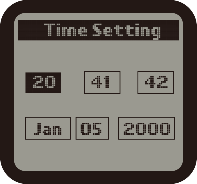
2 ). Time Setting :
Press UP or DOWN, LEFT or RIGHT buttons to select subject and press ENTER to start setting. Press UP or Down for
change and press ENTER button for save. The 1st line is for time (Hour_Minute_Second) and the 2nd line is for date
(Month_Date_Year).

3 ) Override :
When Override function is selected on the System page, the cursor will be flashing. Use UP or DOWN, LEFT or RIGHT
to move to the device you want to manually override (force) to turn on or off. Press ENTER button to active the
override effect. The effectvie time is 10 minutes. After that, the device will be back to its orginal status.
SYSTEM SETTINGS CONTINUED

4 ). CO2 Calibration :
After being used for some time, the CO2 sensor may need to be recalibrated if tolerance occurred.
Press Enter and UP or DOWN button to adjust the calibration level if you have an accurate reference. Otherwise, the
recommended level will be 400. Press Start button to start with the CO2 calibration process.
NOTE : Do NOT exhale or breathe near the sensor while activating the
calibration function.
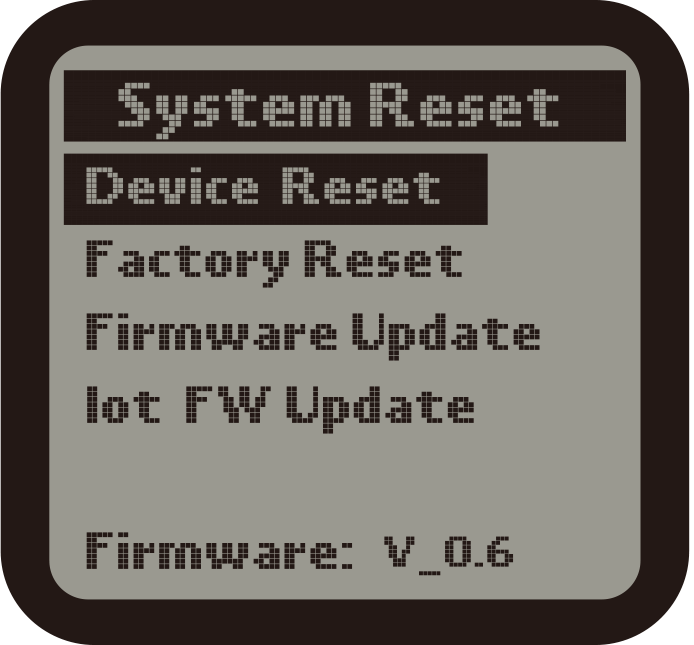
5 ).System Reset :
Devices Reset : When using this function, the unit will delete all addresses
assigned to the connected Device
Stations. User can reconnect Device Stations for resign addresses.
Factory Reset : This function will restore the unit to factory default settings.
Firmware Update : Update a new firmware to fix bugs or add new functions to the
unit. Visit our website to find out update version.
GENERAL INFORMATION
WARRANTY
TrolMaster only uses high quality components. Under normal operating conditions, the mechanical and electronic
components are covered by a three-year warranty from the original date of purchase. For service, return the HCS-1
Hydro-X Control System in the original packaging to your shop with the original sales receipt.
Components that are excluded from warranty are components that have failed due to abnormal usage.
In the case of defects of the HCS-1 Hydro-X Control System, the Controller will either be replaced or repaired
using
new or reconditioned products or parts. If the Controller will be replaced, this limited warranty shall apply to
the replacement product for the remaining initial warranty period, i.e. (three) 3 years from the date of purchase
of the original product.
RETURNS
All returns need to be done in the original packaging in order to avoid damages of the product during transport.
Defective products need to be returned to factory or service shop for repair. Non-professionals DO NOT open the
cabinet to prevent electric shock or damage to the equipment.
REGISTRATION
TrolMaster Agro Instruments Co., Ltd. will occasionally release updated rmware for the HCS-1 Hydro-X Control
System.
By registering your HCS-1 Hydro-X Control System on our
website www.trolmaster.com we can notify you
when an update is available.
We will not sell, rent or share your personal information.

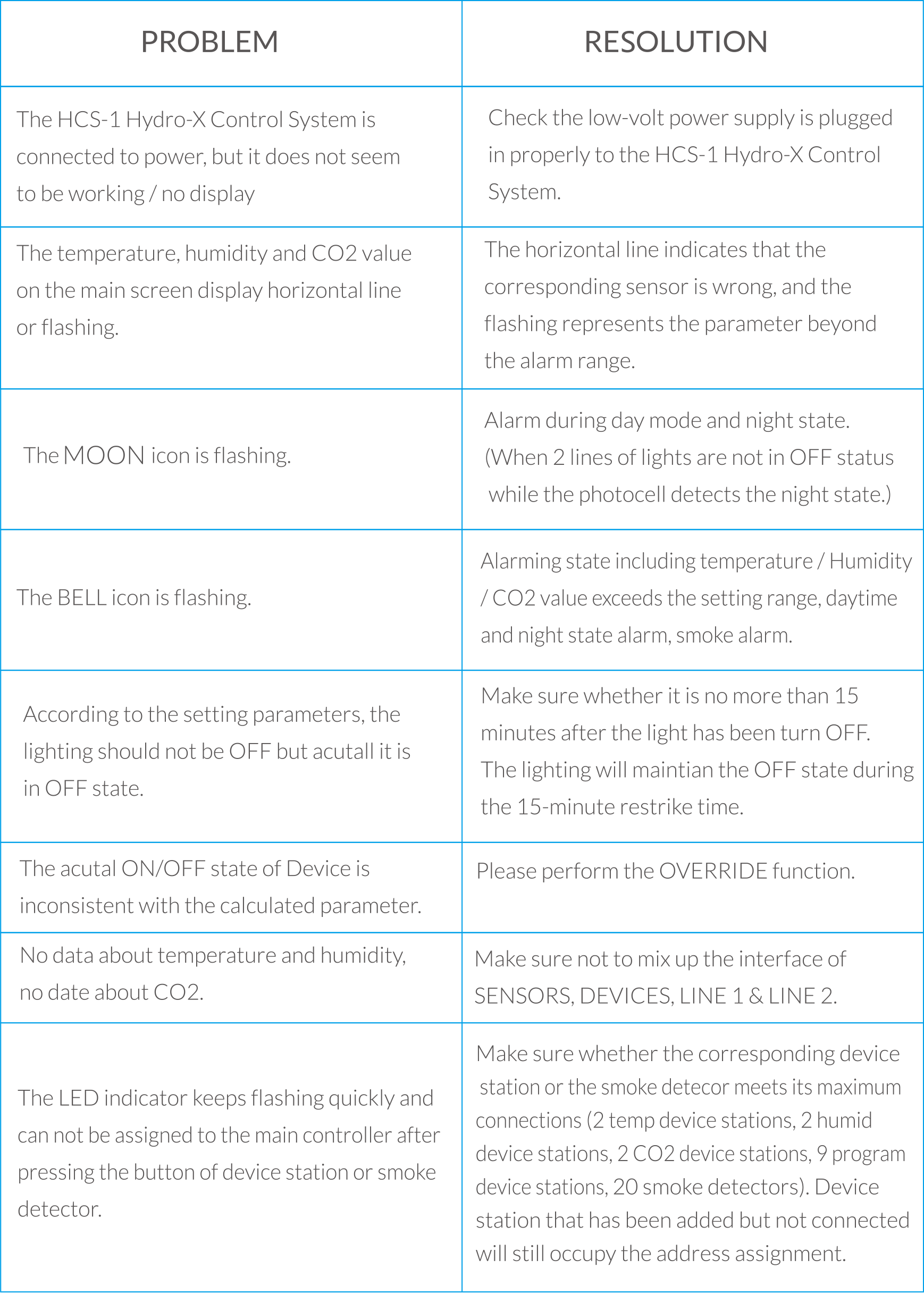
TROUBLESHOOTING
Some of the most common issues or problems can be found within this section. Before returning the
unit for service, please consult the troubleshooting points below, additional information can be found online at
www.trolmaster.com
Troubleshooting Continued
 WARNING :
DO NOT allow the Hydro-X Control
System to be exposed to water or excessive heat. DO NOT open or attempt to repair or disassemble the controller, as
there are no user-servicealbe parts inside. Opening the controller will void the warranty.
If the surface of Hydro-X is dirty, wipe it with a dry towel.
The Hydro-X operates under natural verntilation conditions.
WARNING :
DO NOT allow the Hydro-X Control
System to be exposed to water or excessive heat. DO NOT open or attempt to repair or disassemble the controller, as
there are no user-servicealbe parts inside. Opening the controller will void the warranty.
If the surface of Hydro-X is dirty, wipe it with a dry towel.
The Hydro-X operates under natural verntilation conditions.
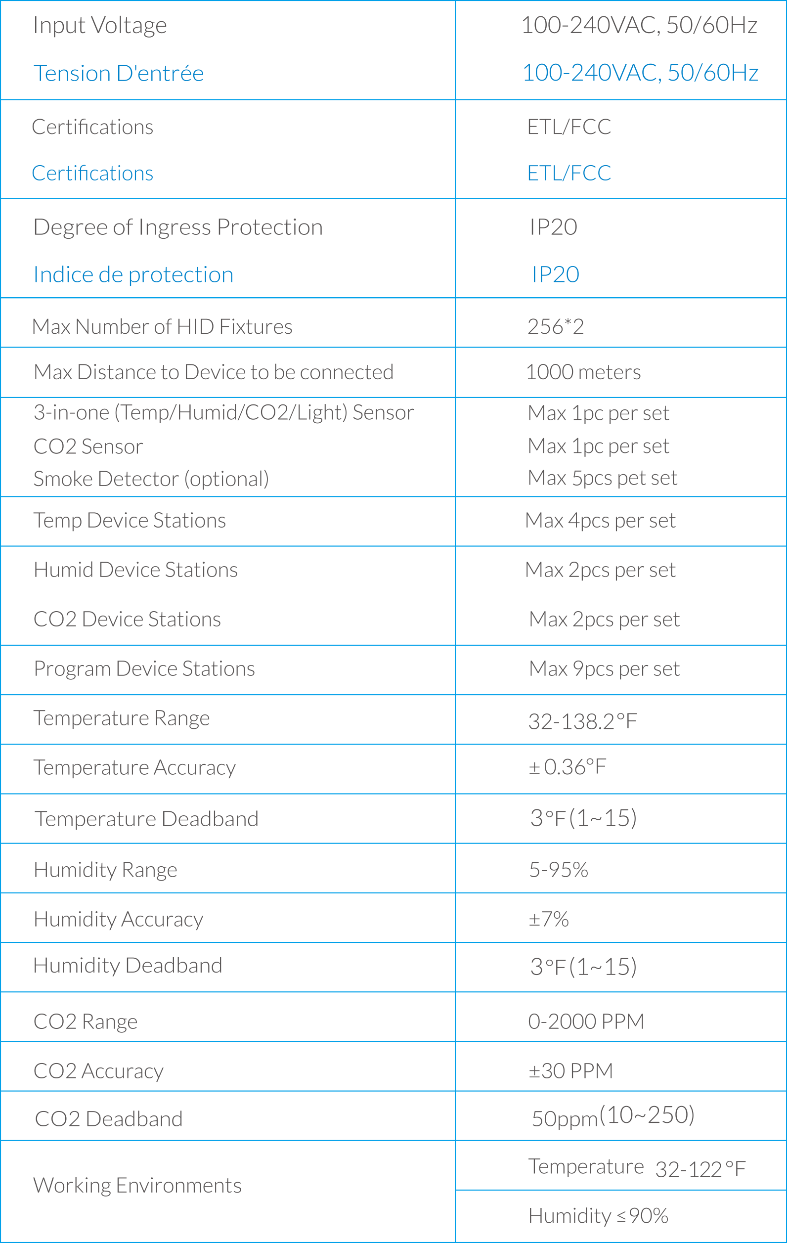
SPECIFICATIONS :
ENVIRONMENTAL AND DISPOSAL CONCERNS:
THIS PRODUCT CONTAINS A BATTERY AND OTHER COMPONENTS WHICH MUST BE
DISPOSED OF PROPERLY.
 This
symbol displayed on a product, its accessories, or its packaging indicates that this product may not be discarded
as household waste. Dispose of the equipment through a recycling center that handles electronics and electrical
appliances. By disposing of the equipment in the proper and lawful way you will be helping to prevent possible
damage to the environment and risk to public health.
This
symbol displayed on a product, its accessories, or its packaging indicates that this product may not be discarded
as household waste. Dispose of the equipment through a recycling center that handles electronics and electrical
appliances. By disposing of the equipment in the proper and lawful way you will be helping to prevent possible
damage to the environment and risk to public health.