PLEASE READ FIRST
Congratulations on your purchase of the NFS-1 Controller. This unit is an efficient way to fully control your
irrigation systems. To ensure safety, please read the manual carefully before installation and follow the
instructions herein. It will provide detailed instructions that will help you to set up the unit, and to understand
its full capability. Any use or application of this product, other than for its original intended purchases are
prohibited. Store this manual in a secure place for future reference.
INTRODUCTION
Aqua-X irrigation Controller is a pioneering and innovational hydroponic irrigation control system. This smartphone
App based system can control up to 30 outputs (24V or 110V) and monitor the pH.EC and water temperature of
nutrient. Water detectors for watering confirmation allow the system to send alerts to user when the watering
schedule fails. With its incredible flexibility,everyone could easily automate their irrigation systems.
The system could control pumps by 110V Control Board and solenoid valves by 24V Control Board. When the massive
control outputs, user could manage delivery schedule for multiple nutrients, multiple rooms and multiple zones.
A sensor board with EC/pH/Temp sensors is also available to allow user to monitor and log all the historical data
of their nutrients. When the measured value exceeds your custom setting range, a warning message will be sent to
your smartphone.
Free smartphone App allows user to monitor and control their watering schedules at their fingertips. Graphic
interface makes multiple schedules easy to adjust and monitor. The innovational watering confirmation feature saves
enormous loss by watering failures.
FACTS
Here are some important things to consider when using the Aqua-X irrigation Controller
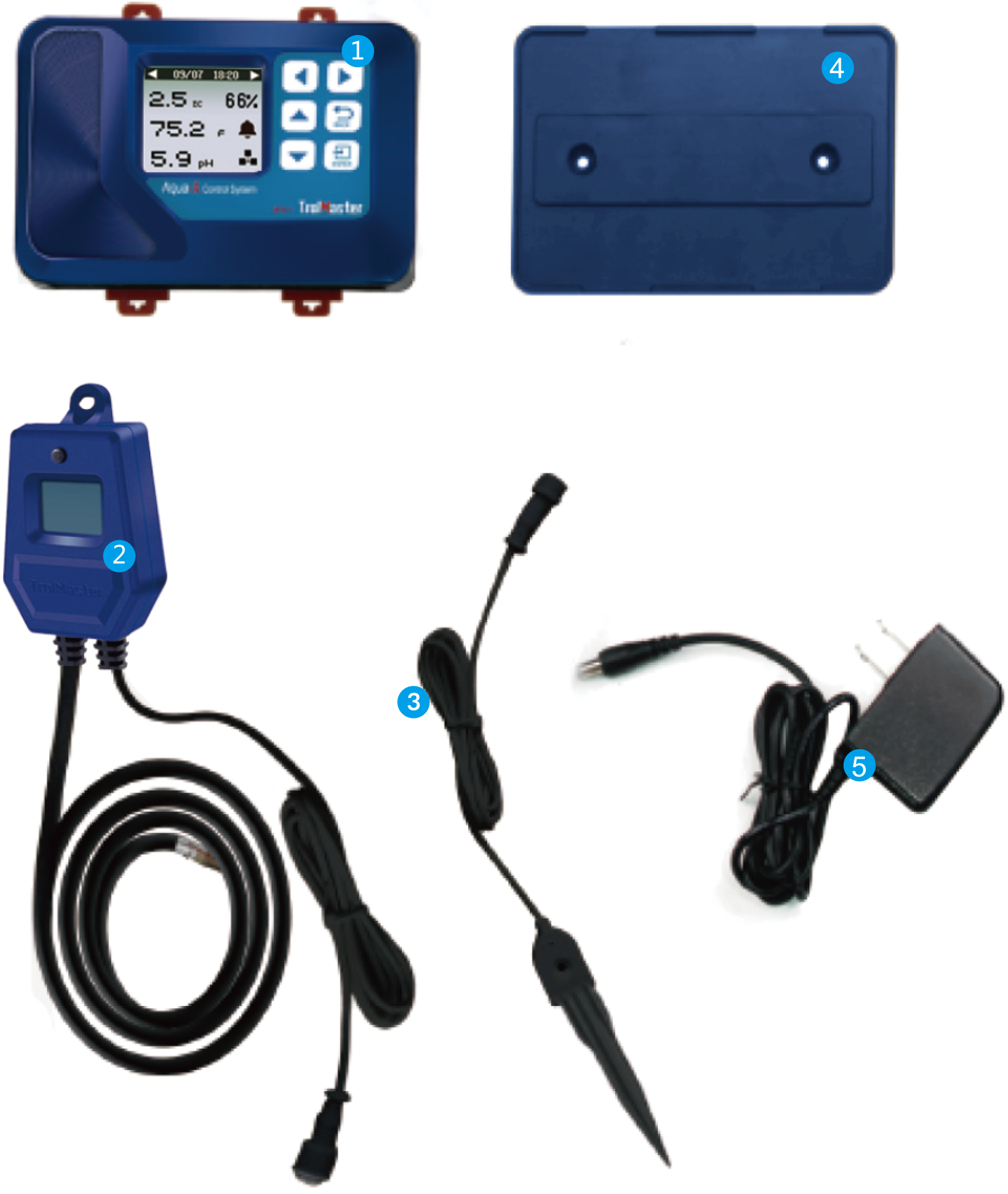
COMPONENTS
INSTALLATION
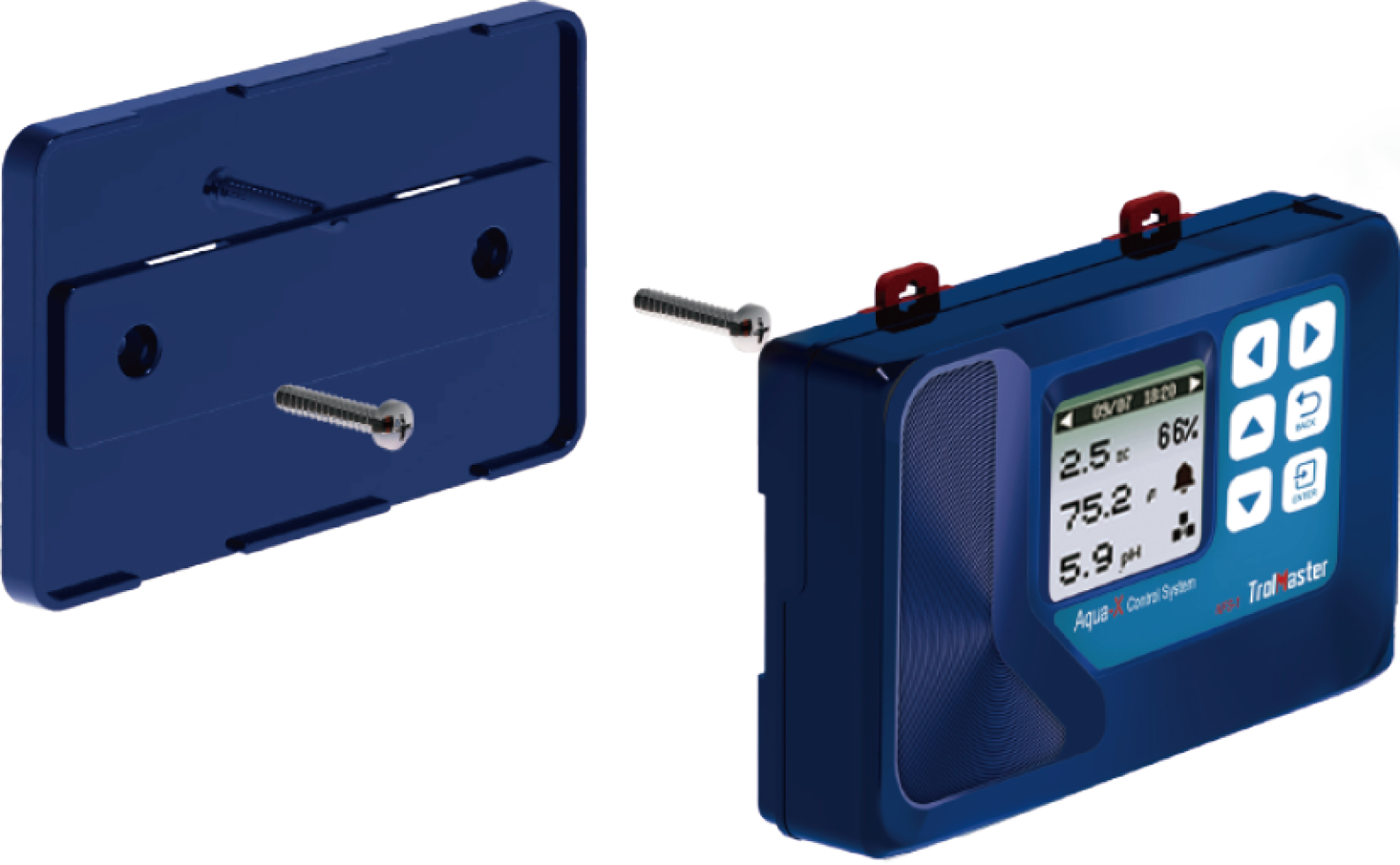
Determine where to locate the main controller. The controller comes with a simple to use DIN type bracket. Pull the
4 tabs outward to release the bracket from the unit, mount th bracket to a wall or surface, place the unit back on
the bracket and press the 4 tabs back in to lock the unit in place.
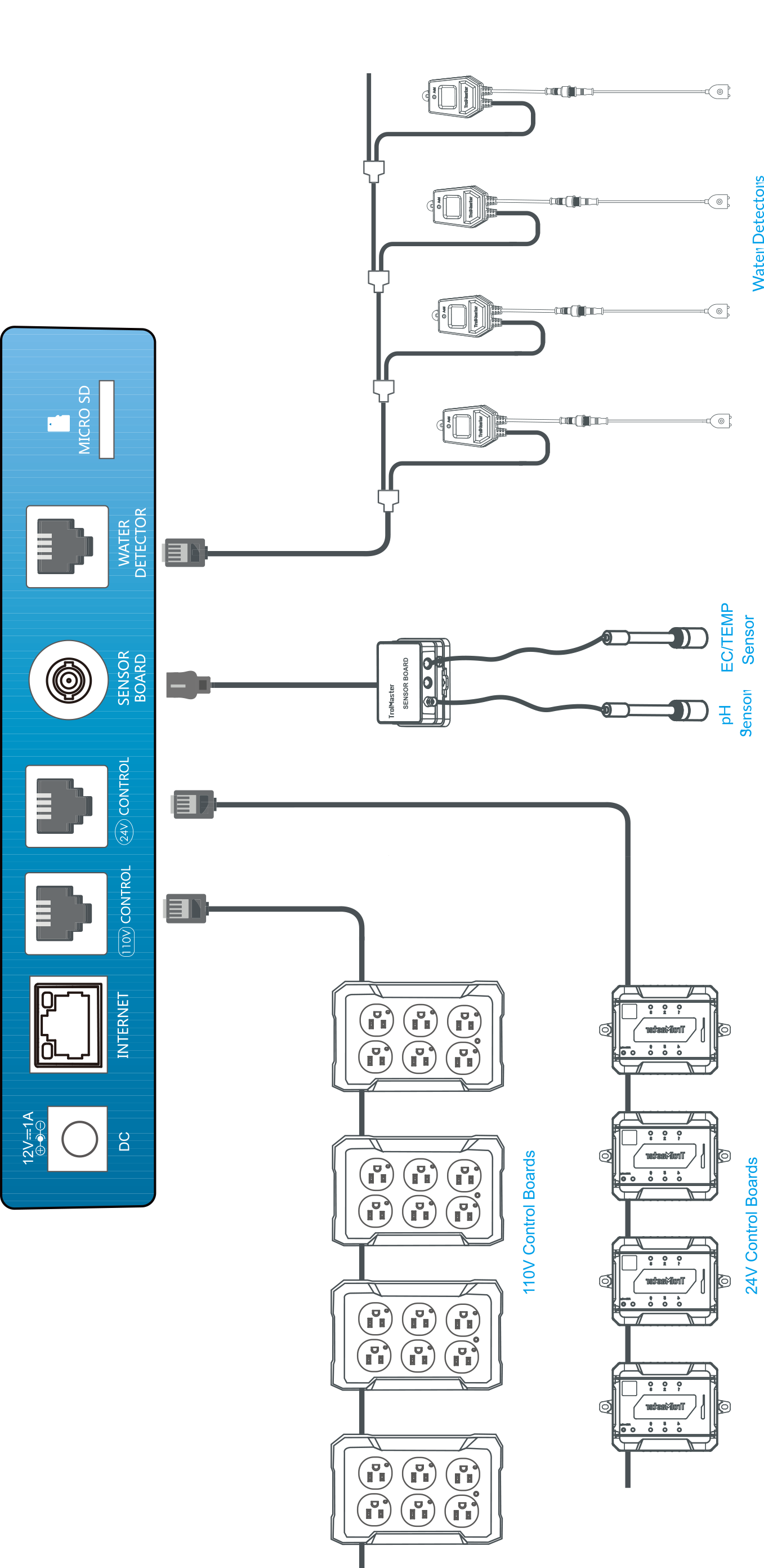
CONNECTIONS
CONNECTIONS CONTINUED…
1. Power Connection :
Connect the plug-in power supply to the power ( DC ) connector on the far left.
2. Control Boards ( 24V or 110V ) Connection :
Connect the 24V Control Board to the Aquo-X with a RJ12 cable going from the 24V CONTROL socket to
the first 24V Control Board to be connected. Plug the 24V Control Board to the wall outlet for power supply. Press
"Addressing" button, the Aqua-X Controller will assign an address to the connected Control Board in sequence. Use
another RJ12 cable to connect to the second 24V Control Board. Repeat this process until all 24V Control Boards (
up to 5pcs for exclusive use ) have been connected to the Aqua-X Controller.
The connection of 110V Control Boards is similar to above processes but through the 110V CONTROL port
3. Program Device Station Connection :
The connection of Program Device Station is similar to the 110V Control Board. The 110V Control Board and Program
Device Station can be chained together with T-Splitter through the 110V CONTROL socket.
4. Water Detectors Connection :
Connect the Water Detector to the Aqua-X with a RJ12 cable going from the Water Detector socket to the first Water
Detector to be connected. Use the T-Splitter and a short RJ cable so that the first cable can continue on to be
connected to the next T-Splitter (Water Detector) to be connected. Press the "Addressing " button, the controller
will automatically assign an address to the Water Detector in sequence. Repeat this process until all Water
Detectors ( up to 30pcs pe set) are connected to the main controller.
5. Sensors Connection :
Connect the Sensor Board to the Aqua-X with a round headed cable ( male-to-male). Connect the pH Sensor and EC/Temp
Sensor to the corresponding connector on the Sensor Board.
6. Internet Connection :
This unit has the feature of connecting the network for remote control. User can use a standard network cable for
connection through the INTERNET socket.
BUTTONS
The NFS-1 Aqua-X Controller is extremely easy to use. The backlit 128x128 LCD display will provide the user with
the current conditions and access all settings. All settings are accessed by using the 6 push buttons on the front
of the unit. The button functions are described below
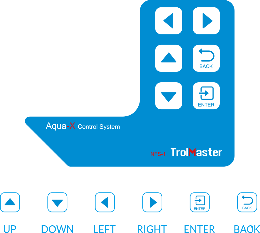
UP / DOWN :The UP and DOWN buttons move the
cursor up and down
to select the item on the LCD display.
LEFT / RIGHT :The LEFT and RIGHT buttons move
the cursor to previous page or next page, left item or right item.
BACK :The BACK button goes backwards to the
previous page.
ENTER :The ENTER button is used to open the
menu item to be changed as well as to accept and save the new setting.
Familiarize yourself with the function of the 6 buttons on the front of the NFS-1 Controller in order to be able to
access settings, and to better understand how to use the NFC-1 Control Systems to its greatest potential.
START SETTINGS
Once you have connected 24V Control Board. 110V Control Board(s), Sensor Board(s) and Water Detectors to the NFS-1
Controller, we can start using the unit.
Connect the plug-in power supply to the power connector on the buttom of the NFS-1 Controller. NFS-1 Controller
will turn on and boot up.
If it is the first time you have used the NFS-1 Controller, when you power on the NFS-1 Controller, the Welcome
screen / page will display and remind user to press " ENTER" to set system time.
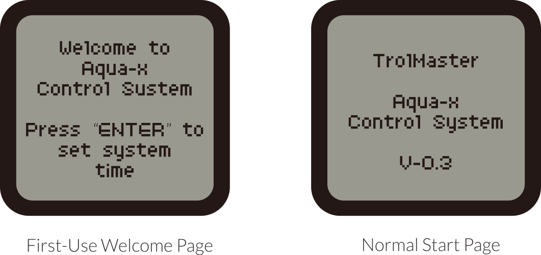
NOTE : Press the ENTER button to set system time before use.
Time Setting : please refer to P23 for the time setting so as to
change the default time into the current time before use.
MAIN MENU
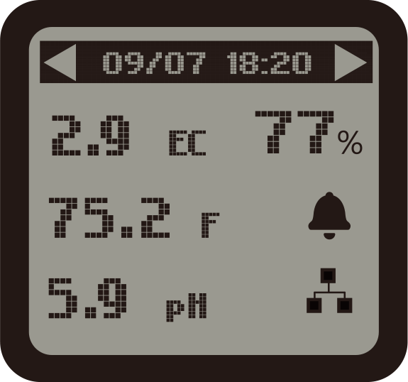
The main menu displays three elements
EC Value e.g.2.9
pH Value e.g.5.9
Water Temperature Value (°F) e.g.: 75.2°F
Water Content Value e.g.:77%
The top title bar indicates current date & time.
Month/Day
Hour/Minute
Icon Indication
Alarm Activated

Internet Connected

NOTE : Download the TrolMaster App from APP Store or Google
Play
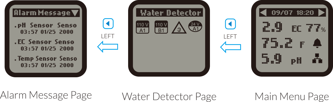
1 ) On the Main Menu page, press LEFT button  to get access to Water Detector page. It shows output(s) that has
(have)
been associated with the connected Water Detector. Press LEFT button again, the LCD screen will show the
Alarm Message page. The LCD screen will show records of all alarm messages.
to get access to Water Detector page. It shows output(s) that has
(have)
been associated with the connected Water Detector. Press LEFT button again, the LCD screen will show the
Alarm Message page. The LCD screen will show records of all alarm messages.
to get access to Water Detector page. It shows output(s) that has
(have)
been associated with the connected Water Detector. Press LEFT button again, the LCD screen will show the
Alarm Message page. The LCD screen will show records of all alarm messages.
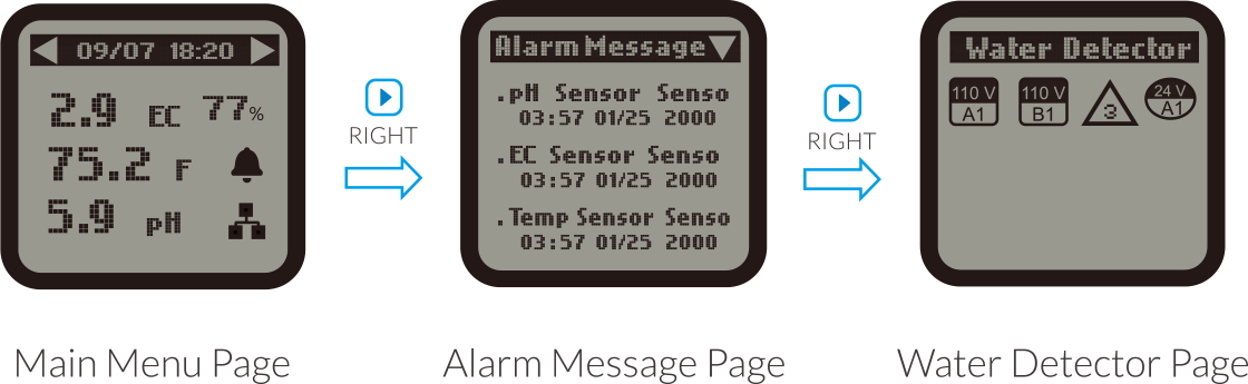
2 ) On the Main Menu page, press RIGHT button  to get access to Alarm Message page. The LCD screen will show record
of all alarm messages. Press RIGHT button again, the LCD screen will show the Water Detector page. It shows the
only output ( 110V or 24V) that has been associated with the connected Water Detector.
to get access to Alarm Message page. The LCD screen will show record
of all alarm messages. Press RIGHT button again, the LCD screen will show the Water Detector page. It shows the
only output ( 110V or 24V) that has been associated with the connected Water Detector.
to get access to Alarm Message page. The LCD screen will show record
of all alarm messages. Press RIGHT button again, the LCD screen will show the Water Detector page. It shows the
only output ( 110V or 24V) that has been associated with the connected Water Detector.
NOTE : Hot-plug is not recommended for the
MicroSD card on the main page. Damage to the files within the MicroSD card is a possible result.
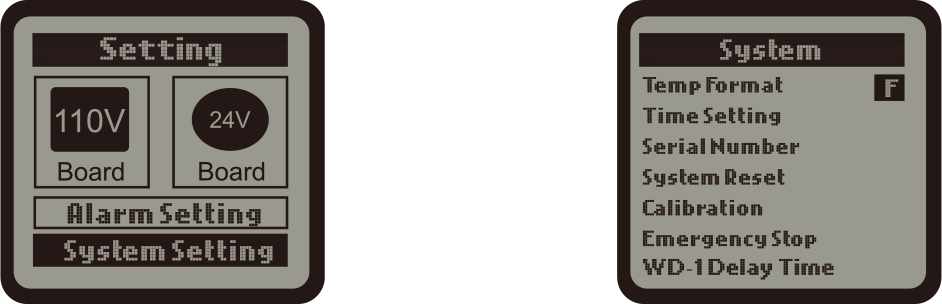
SETTING PAGE
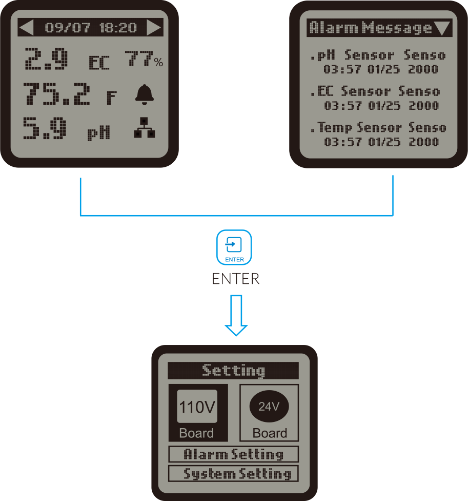
On the Main Menu page or Alarm Message page press  ENTER button to get access to the SETTING page. The LCD screen
will display 4 subjects ( 110V Board. 24V Board. Alarm Setting and System Setting) as shown on above picture. You
can press the respective button (UP/DOWN/LEFT/RIGHT) to select the subject that you want to adjust the setting.
ENTER button to get access to the SETTING page. The LCD screen
will display 4 subjects ( 110V Board. 24V Board. Alarm Setting and System Setting) as shown on above picture. You
can press the respective button (UP/DOWN/LEFT/RIGHT) to select the subject that you want to adjust the setting.
ENTER button to get access to the SETTING page. The LCD screen
will display 4 subjects ( 110V Board. 24V Board. Alarm Setting and System Setting) as shown on above picture. You
can press the respective button (UP/DOWN/LEFT/RIGHT) to select the subject that you want to adjust the setting.
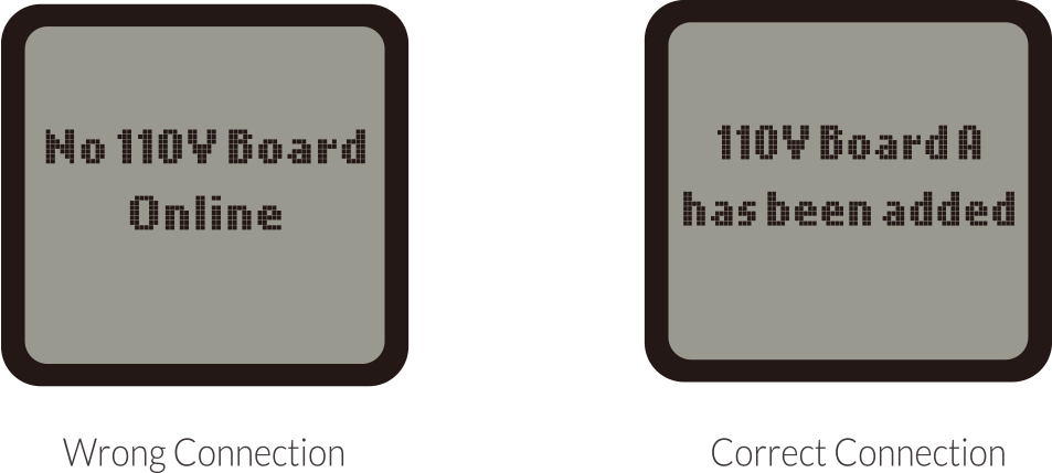
110V BOARD SETTING
When the RJ12 cable is not correctly connected to the corresponding 110V CONTROL port or the 110V Control Board is
not connected to the power supply, the LCD screen will show "No 110V Board Online". Please make sure the RJ12 cable
is correctly connected and power on the 110 Control Board. After power-on, the Addressing LED indicator will keep
flashing every second. Then press the ADDRESSING button on the 110V Control Board, the LCD screen will display"110V
Board A has been added". The first connected Control Board will be marked as "A", and the second one marked as "B",
the third as "C", and so on.
On the SETTING page, press ENTER button to enter the 110V Control Board list page. The connected Control Board(s)
will be shown page to page. User can press RIGHT button to select the 110V Control Board ( A.B.C…) for the setting
change.
When the Control Board selected press ENTER button and the 1st output will be highlighted and blinking. Press LEFT,
RIGHT, UP or DOWN button to select the output such as 110V A1. Press ENTER button to confirm and enter the SETTING
page of that output.
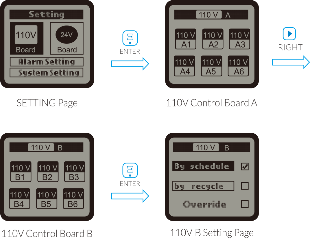
On the SETTING page of selected output such as 110V A1 press ENTER button and the tick icon on the "By schedule"
will be highlighted and blinking. You can also press DOWN button to select"By recycle". Press ENTER button to
confirm and save the setting.
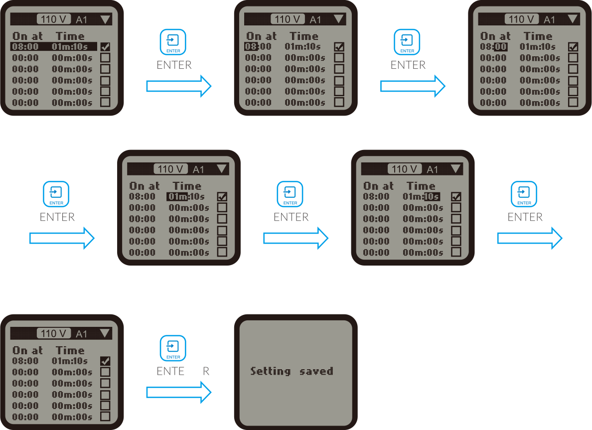
a. By schedule.
Once the "By schedule" setting is selected, user can press ENTER button to activate the setting for the 1 line of
total 12 lines of schedules. The HOUR of " On at" time will be highlighted and blinking, which means that it's
ready for change. User can press UP or DOWN button to change the HOUR. Press ENTER button and the MINUTE of "On at"
will be highlighted and blinking, user can press UP or DOWN button to change the minute. Press ENTER button and the
MINUTE of " Time" will be highlighted and blinking, user can press UP or DOWN button to change the minute. Press
ENTER button and the SECOND will be highlighted and blinking, user can press UP or DOWN button to change the
second. Press ENTER button and the tick symbol will be highlighted and blinking. Finally, press ENTER button to
confirm and save the changes and the LCD screen will display " Setting saved".
Similarly, user can change the "On at" & "Time" for other schedule (up to 12 lines) as above processes.
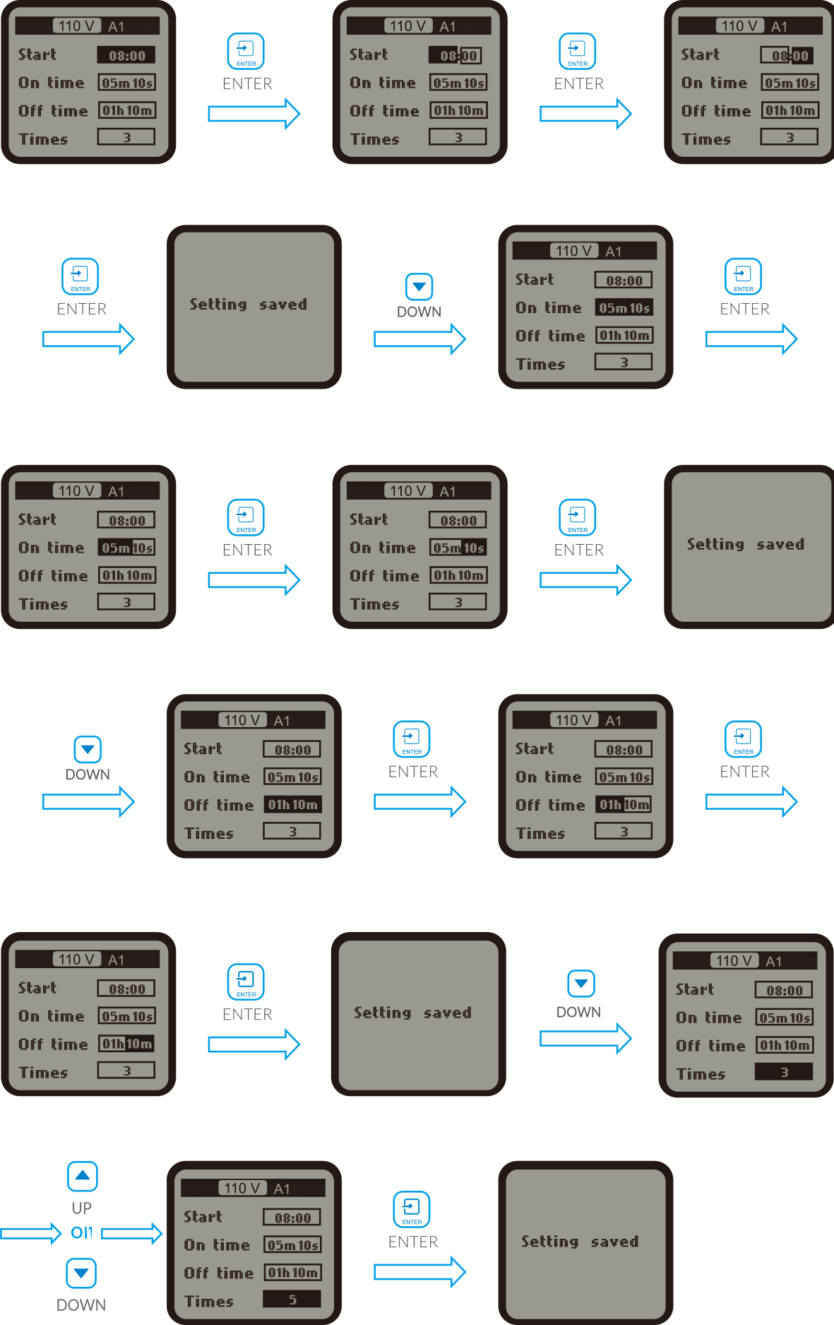
b. By recycle:
Once the "By recycle" setting is selected, user can press "UP" or "DOWN" button to select "Start". "On time" & "
Times" for change. Press ENTER button to activate the setting.For example, when "Start" selected, press ENTER
button and the HOUR will be highlighted and blinking, user can press UP or DOWN button to change the hour. Press
ENTER button and teh MINUTE will be highlighted and blinking, press UP or DOWN button to change the minute.
Finally, press ENTER button to confirm and save the change and the LCD screen will be display " Setting saved"
Similarly, user can change the "On time". "Off time" and "Times" accordingly.
24V BOARD SETTING
The setting of 24V Board Setting is similar to the 110V Board Setting.
WATER DETECTOR SETTING
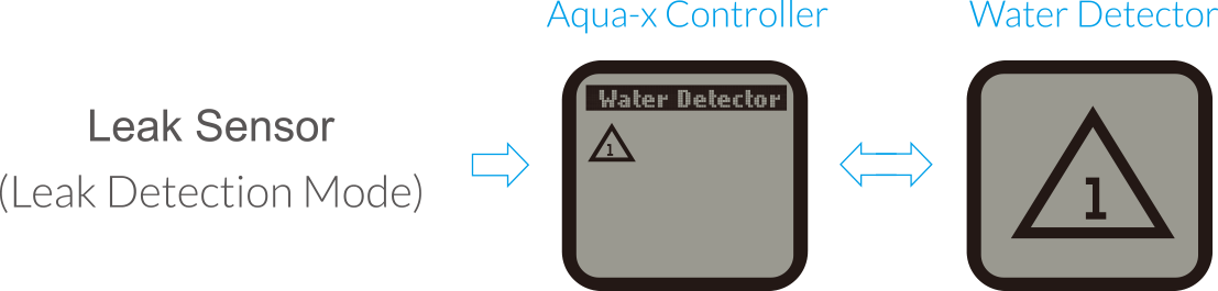
a) Leak Sensor ( Leak Detection Mode)
The default function of Water Detector ( WD-1) is to do leak detection and the symbol is a triangle shown in the
Aqua-X Controller. When WD-1 detects water leakage, it will send alarm message to your Smartphone one minute later.
You can also check the alarm message in the Aqua-X Controller.
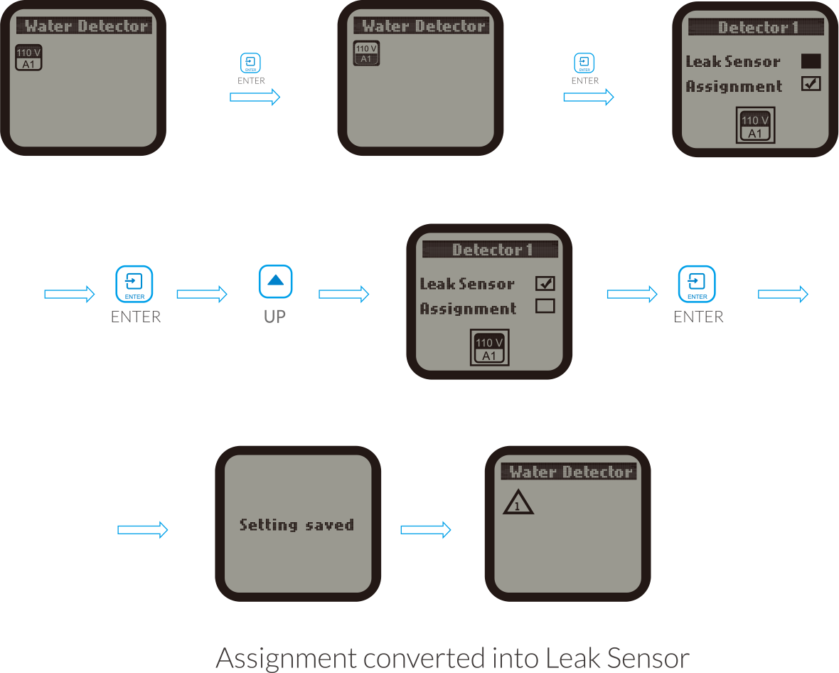
If the Water Detector is NOT in original default function ( leak sensor ), you can change the Assignment into Leak
Sensor as above processes.
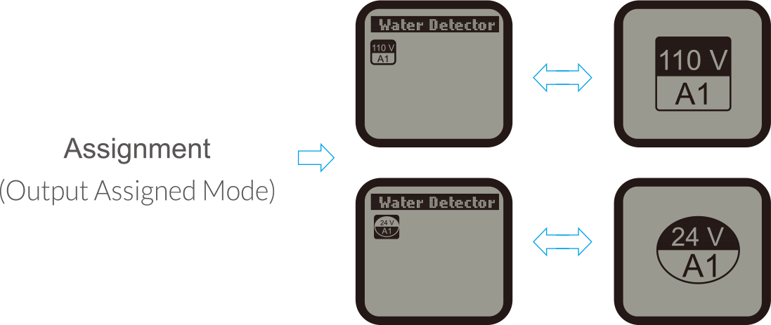
b) Assignment ( Output Assigned Mode )
The default mode of Water Detector is in Leak Sensor ( Leak Detection Mode). You can change the Leak Detection Mode
( Leak Sensor ) into Output assigned Mode ( Assignment ) as below processes. As one Water Detector can be assigned
to only one output on any Control Board, you need to select 24V or 110V and one of six outputs to be assigned with
the Water Detector. When the output has been successfully assigned, the Water Detector will send alarm message to
your Smartphone one minute later when it detects no water on the reservoirs of the irrigation system.
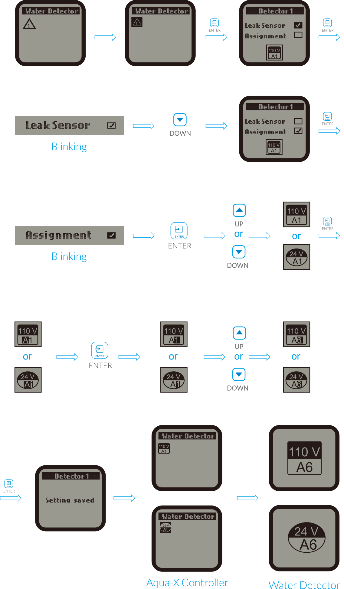
NOTE :
1. Each Water Detector can be assigned to a Control Board which has been successfully assigned to the Aqua-X
Controller. The Water Detector can not be assigned to an unassigned Control Board.
2. One Water Detector can be assigned to only one 24V or 110V output. One Aqua-X Controller can connet up to 30pcs
Water Detectors.
3. If the assigned output of that board is offline, the output symbol will blink on the LCD display of the Aqua-X
Controller.
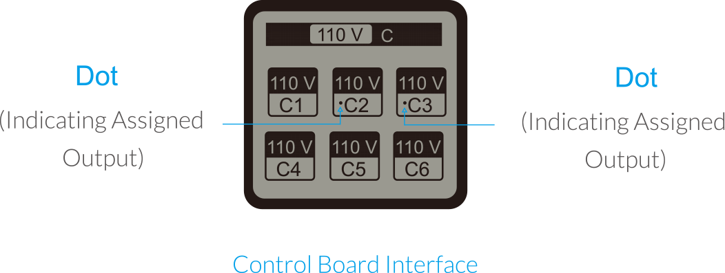
4. If the output is successfully assigned with the Water Detector and the Water Detector is connected with the
Aqua-X Controller, there is a dot before the assigned output on the Control Board interface as below illustration.
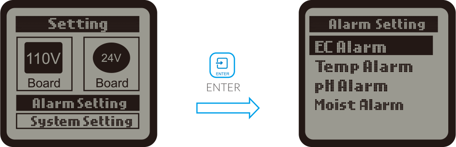
ALARM SETTING
On the Setting page, press DOWN button to select the Alarm Setting, Press ENTER button and the LCD screen will
display three Settings for selection EC Alarm. Temp Alarm and pH Alarm. User can press UP button or DOWN button to
select anyone of them for setting.
a. EC Alarm
When the EC Alarm is selected, press ENTER button to enter the EC Alarm setting page.The LCD screen will display
the MIN value and MAX value. Press ENTER button to activate the setting page and the MIN value will be highlighted
and blinking. Press UP button or DOWN button to change the MIN value, then press the ENTER button to confirm and
save the change. The LCD screen will show "Setting saved".
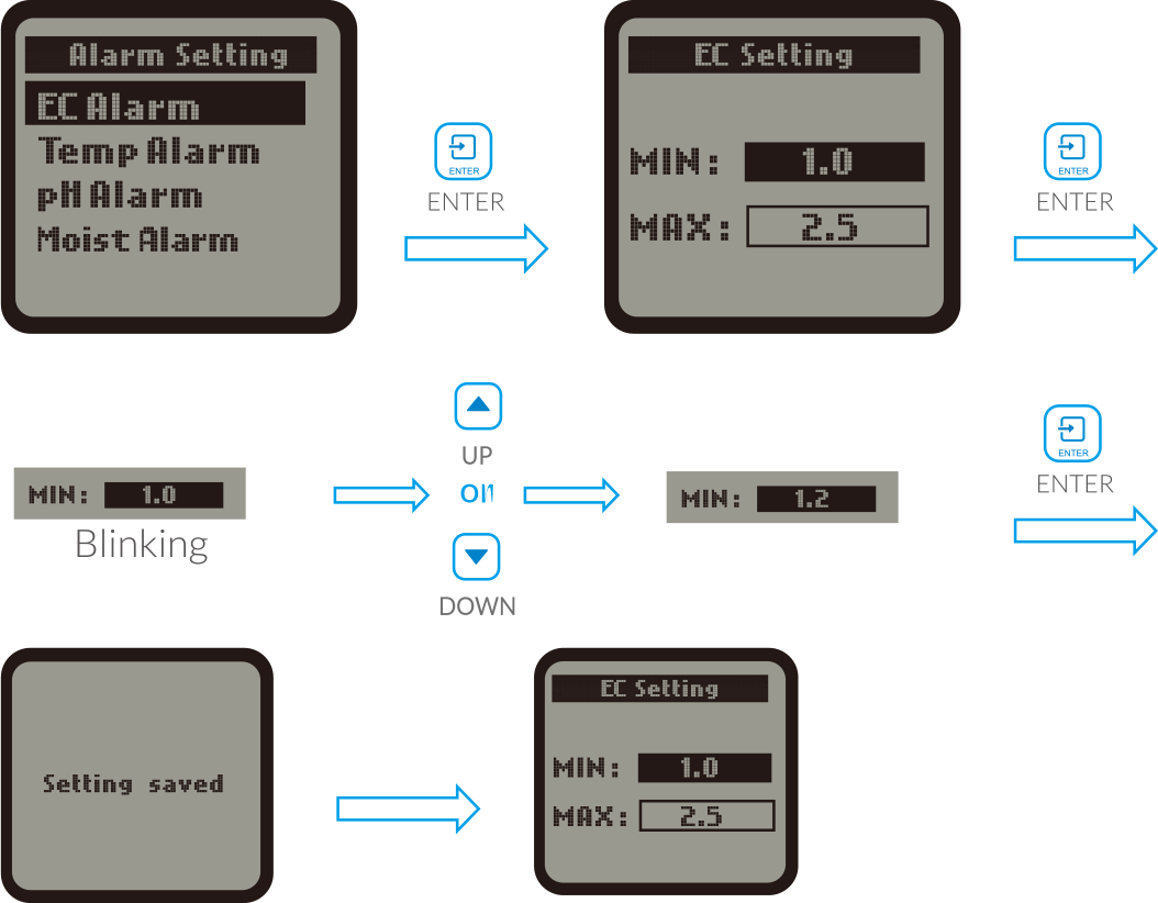
User can also press DOWN button to select the MAX value directly for change. If keeps unchanged for the MIN value.
The setting of MAX value is similar to setting of MIN value.
b. Temp Alarm
When the Temp Alarm is selected, press the ENTER button to enter the Temp Alarm setting page. The LCD screen will
display the MIN value and the MAX value. Press ENTER button to activate the setting page and the MIN value will be
highlighted and blinking. Press UP button or DOWN button to change the MIN value, then press the ENTER button to
confirm and save the change. The LCD screen will show "Setting saved".
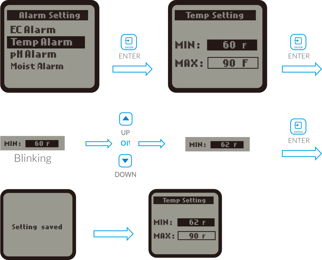
User can also press DOWN button to select the MAX value directly for change. If keeps unchanged for the MIN value.
The setting of MAX value is similar to setting of MIN value.
c. pH Alarm
When the pH Alarm is selected, press the ENTER button to enter the pH Alarm setting page. The LCD screen will
display the MIN value and the MAX value. Press ENTER button to activate the setting page and the MIN value will be
highlighted and blinking. Press UP button or DOWN button to change the MIN value, then press the ENTER button to
confirm and save the change. The LCD screen will show "Setting saved".
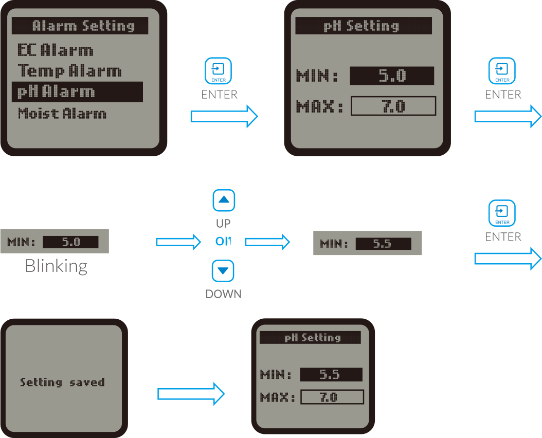
User can also press DOWN button to select the MAX value directly for change. If keeps unchanged for the MIN value.
The setting of MAX value is similar to setting of MIN value.
SYSTEM SETTING
On the Setting page, press DOWN button to select the System Setting, Press ENTER button and the LCD screen will
display five Settings for selection: Temp Format, Time Setting and Serial Number, System Reset, Calibration. User
can press UP button or DOWN button to select anyone of them for setting.
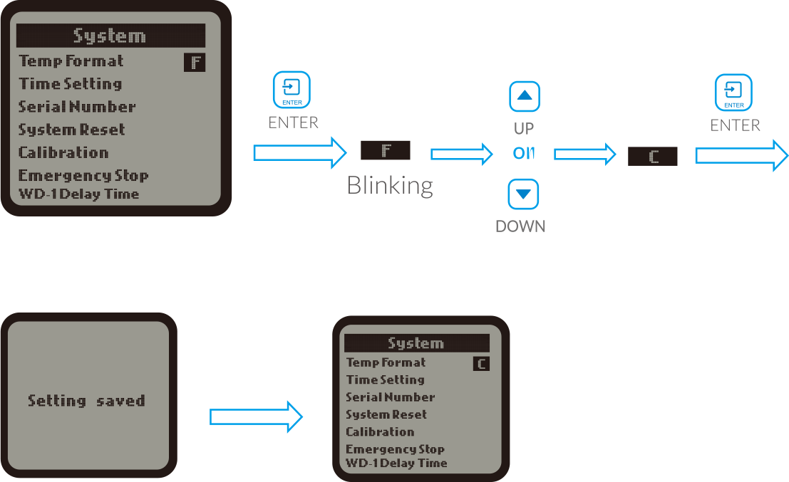
a. Temp Format
When the Temp Format is selected, press the ENTER button and the temperature sysbol F or C will be highlighted and
blinking. Press UP button or DOWN button to covert the temperature format betwen F and C. Finally, press ENTER
button to confirm and save the change. The LCD screen will show "Setting saved".
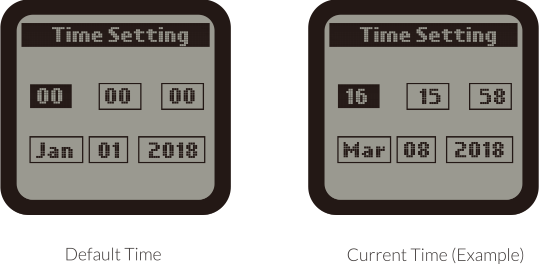
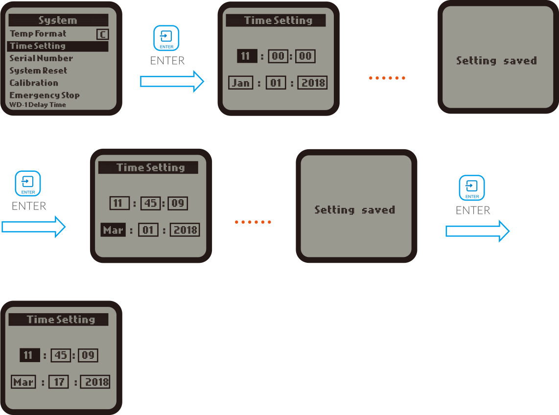
b. Time Setting
When the Time Setting is selected, press the ENTER button and the LCD screen will display will show the default
time if it's the first time to use this unit. The time consists of two lines:
1st line :
HOUR: MINUTE: SECOND
2nd line :
MONTH: DATE: YEAR
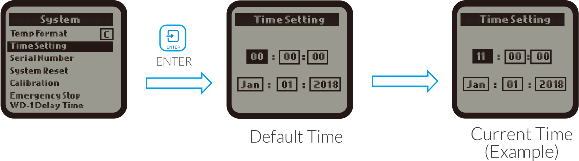
Press ENTER button and the HOUR will be highlighted and blinking, Press UP or DOWN button to change the hour. Press
ENTER button again and the cursor will skip to the next, the MINUTE will be highlighted and blinking. Similarly,
you can change the MINUTE and SECOND. When the 1st line of time ( HOUR:MINUTE:SECOND) has been changed, press ENTER
button and the LCD screen will display" Setting saved"
The date setting(MONTH:DATE:YEAR) is similar to above time setting
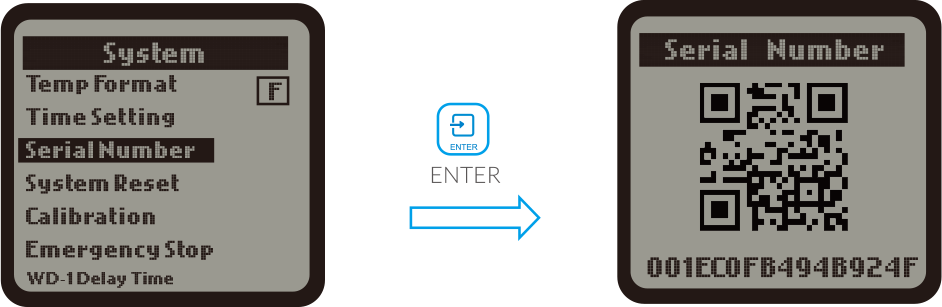
c. Serial Number
When the Serial Number column is selected, press ENTER button and the LCD display will show the QR code and serial
number
d. System Reset
When the System Reset column is selected, press ENTER button and the LCD display will show Device Reset,
Factory reset, Firmware Updated lot FW Update. Press UP button or DOWN button to select anyone of them for setting.
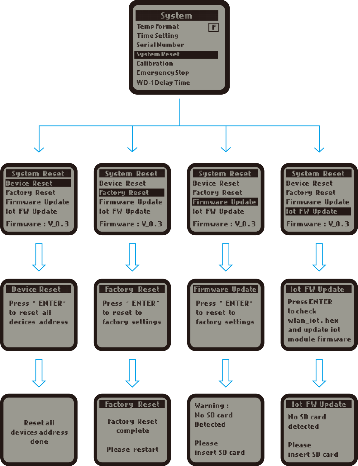
NOTE : For the Firmware Update and lot FW Update, make sure to
insert the MicroSD card with the latest version of upgrade software
e. Calibration
When the calibration column is selected, press ENTER button and the LCD display will show Calibrate EC,
Calibrate Ph7.0, Calibrate Ph4.0. Press UP button or DOWN button to select anyone of them for calibration.
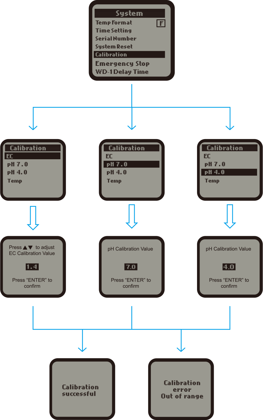
NOTE :
1). Please note there are two results for the calibration. One is successful, the other is unsuccessful ( failure
).
2). Please calibrate pH7.0 first. Calibration pH4.0 should be processed after the calibration pH7.0 within half an
hour.
3). Before calibration, the corresponding probe should be placed in the corresponding standard solution and allowed
to stand for more than 1 minute.
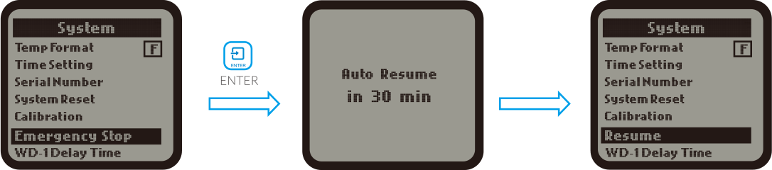
f. Emergence Stop
The Emergency Stop function can be selected when there is abnormal condidtion found on the Control Boards. Press
the DOWN button to select "Emergency Stop" and then press the ENTER button to confirm your selection. The LCD
screen of Aqua-X will show "Auto Resume in 30 min" and then show " Resume" automatically in 30 minutes. If without
midway intervention by pressing the ENTER button. On the same interface, press the ENTER button again. the
Emergency Stop function will be activated again.
NOTE :
1. When the "Emergency Stop" function is selected, all devices on all boards ( 24V & 110V ) will stop working for
half an hour and then resume to work in 30 minutes. Press the ENTER button again and all devices on all the boards
will stop working for another half an hour.
2. In the stop mode, press the ENTER button within 30 minutes and the stop mode will be cancelled immediately, and
return to normal working state.
GENERAL INFORMATION
WARRANTY
Aqua-X Irrigation Controller ( NFS-1 ) only uses high quality components. Under normal coperating conditions, the
mechanical and electronic components are covered by a three-year warranty from the original date of purchase. For
service, return the NFS-1 Irrigation Controller in the original packaging to your shop with the original sales
receipt.
Components that are excluded from warranty are components that have failed due to abnormal usage.
In the case of defects of the Aqua-X Irrigation Controller ( NFS-1 ), the Controller will either be replaced or
repaired using new or reconditioned products or parts. If the Controller will be replaced this limited warranty
period, i.e.( three ) 3 years from the dateof purchase of the original product.
RETURNS
All returns need to be done in the original packaging in order to avoid damages of the product during transport.
Defective products need to be returned to factory or service shop for repair. Non-professionals DO NOT open the
cabinet to prevent electric shock or damage to the equipment.
a). Please use TrolMaster's components for better performance.
b) In the case of defects of the Aqua-X Controller, the Aqua-X Controller will either be replaced or repaired using
new or reconditionaled products or parts by TrolMaster within three-year warranty from the original date of
purchase. For service, return the Aqua-X Controller in good packaging to our agent with the original receipt.
c) Non-professionals DO NOT open the cabinet to prevent electric shock or damage to the Aqua-X Controller.
ENVIRONMENTAL AND DISPOSAL CONCERNS:
THIS PRODUCT CONTAINS A BATTERY AND OTHER COMPONENTS WHICH MUST BE DISPOSED OF PROPERLY
 This
sysbol displayed on a product, its accessories, or its packaging indicates that this product may not be discarded
as household waste. Dispose of the equipment through a recycling center that handles electronics and electrical
appliances. By disposing of the equipment in the proper and lawful way you will be helping to prevent possible
damage to the environment and risk to public health.
This
sysbol displayed on a product, its accessories, or its packaging indicates that this product may not be discarded
as household waste. Dispose of the equipment through a recycling center that handles electronics and electrical
appliances. By disposing of the equipment in the proper and lawful way you will be helping to prevent possible
damage to the environment and risk to public health.
TROUBLESHOOTING
Some of the most common issues or problems can be found within this section. Before returning the unit for service,
please consult the troubleshooting points below, additional information can be found online at www.troulmaster.com
.png)
 WARNING
: DO
NOT allow the the Aqua-X Controller to be exposed to water or excessive heat. DO NOT open or attempt to repair or
disassemble the Aqua-X Controller, as there are no user-serviceable parts inside. Opening the controller will void
the warranty.
1. If the surface of the Aqua-X Controller is dirty, wipe it with a dry towel.
2. The Aqua-X Controller is designed for indoor use only, it should be operated under natural ventilation
conditions.
3. For safety, it is necessary to connect the ground wire. If a short circuit did occur, the current would flow
through the ground wire, causing a blown fuse or tripped circuit breaker.
4. The Aqua-X Controller should be positioned in a place that it’s easily to be pulled out when a fault occurs.
WARNING
: DO
NOT allow the the Aqua-X Controller to be exposed to water or excessive heat. DO NOT open or attempt to repair or
disassemble the Aqua-X Controller, as there are no user-serviceable parts inside. Opening the controller will void
the warranty.
1. If the surface of the Aqua-X Controller is dirty, wipe it with a dry towel.
2. The Aqua-X Controller is designed for indoor use only, it should be operated under natural ventilation
conditions.
3. For safety, it is necessary to connect the ground wire. If a short circuit did occur, the current would flow
through the ground wire, causing a blown fuse or tripped circuit breaker.
4. The Aqua-X Controller should be positioned in a place that it’s easily to be pulled out when a fault occurs.
REGISTRATION
TrolMaster Agro Instruments Co.,Ltd. will occassionally release updated firmware for the Aqua-X Irrigation
Controller ( NFS-1 ).
By registering your NFS-1 Irrigation controller on our website www.trolmaster.com
, we can notify you when an update
is available
We will not sell, rent or share your personal information.

SPECIFICATIONS
.png)
Remarks : combined application is available for 24V Control Board
( 6 outputs each ), 110V Control Board ( 6 outputs each ) and Program Device Station ( 1 output each ) but control
up to 30 outputs per set