Thank you for purchasing our OA6-110 110V Control Board.
A 110V Control Board is specially designed for Aqua-X Irrigation Control System. It features 6 individual 110V
outputs for the pump control in the Aqua-X Control System. Water pumps are the basic component in automatic flow
control in the irrigation system.
With the use of 110V Control Board(s), the Aqua-X Irrigation Control System could manage up to 30 individually
controlled 110V outputs (used to control water pumps) for multiple watering plans (by schedule or by recycle). With
the massive control outputs, user could manage water delivery schedules easily for multiple nutrients, multiple
rooms and multiple zones.
If you have any questions, please contact us:
Overview
TrolMaster ( Xiamen ) Electronics Co.,Ltd.
2/F, Building A, No.600 West Dongren 2nd Road, Jimei District, Xiamen, China
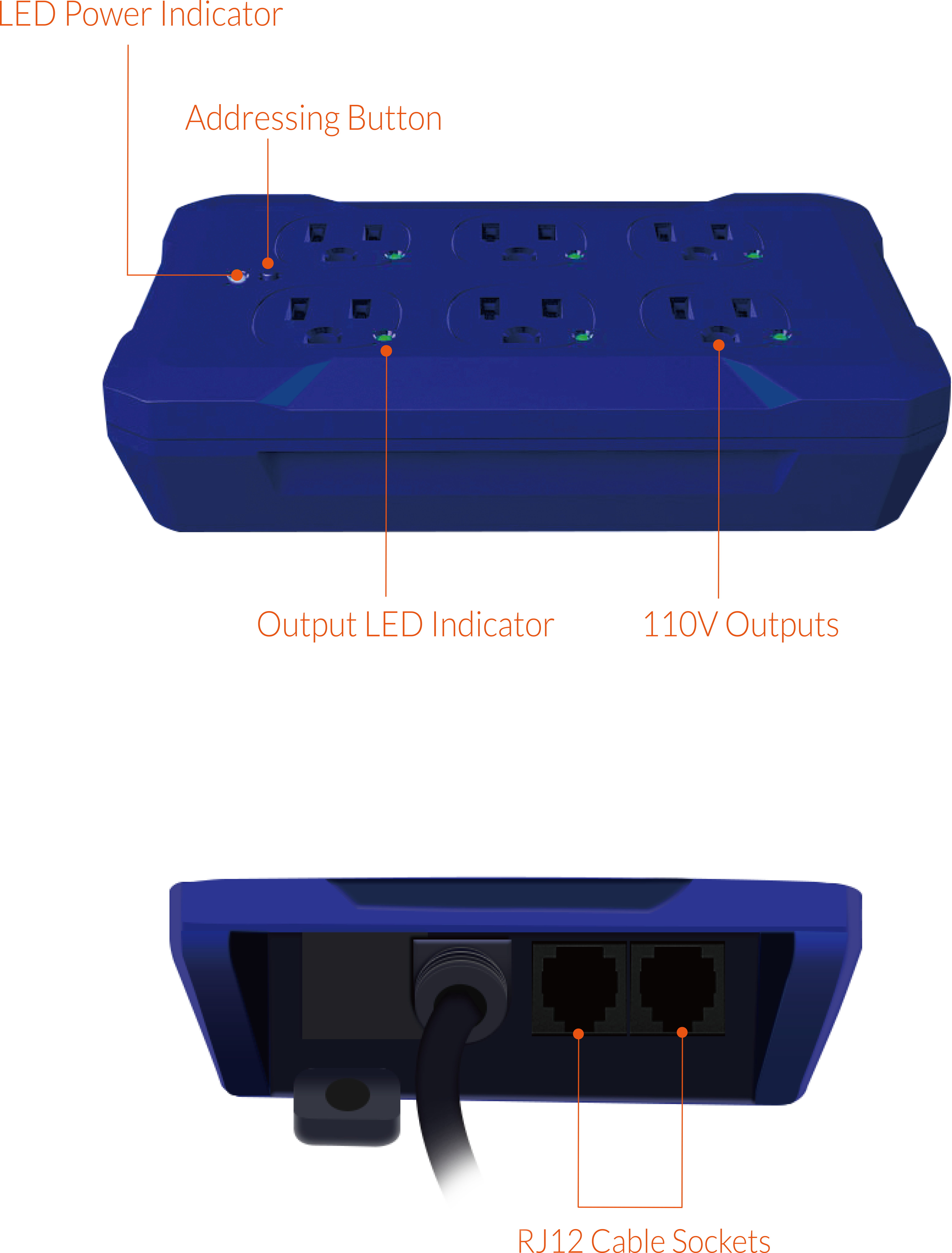
Features
Operation Instructions
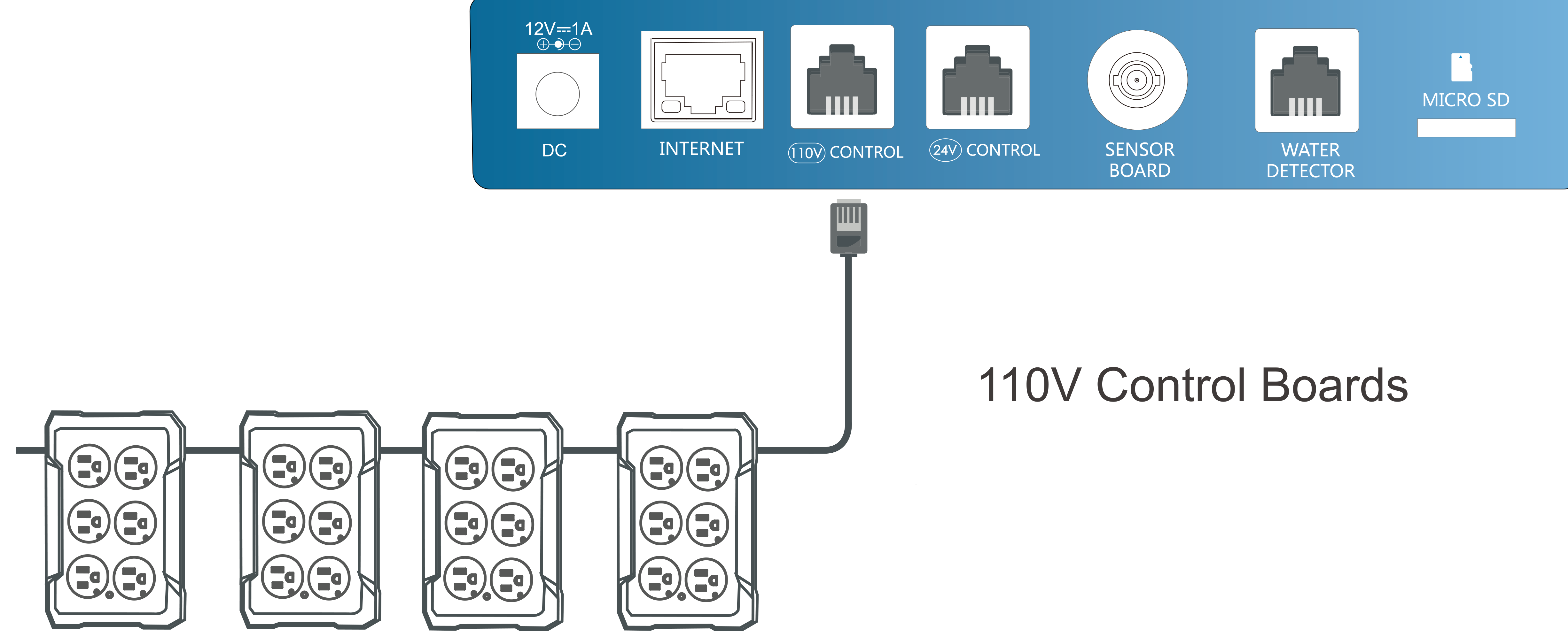
1. Connection to Aqua-X
Use a RJ12 Cable to connect the first 110V Control Board to the Aqua-X Controller. Plug the RJ12
cable connector into the 110V CONTROL port on the bottom of the Aqua-X Controller. Then plug the opposite RJ12
cable connector into the RJ12 cable socket on the either side of the first 110V Control Board.
Use another RJ12 cable to connect the second 110V Control Board. Plug the RJ12 cable connector into the RJ12 cable
socket on the opposite side of the first 110V Control Board. Then plug the opposite RJ12 cable connector into the
RJ12 cable socket on the either side of the second 110V Control Board.
Other 110V Control Boards can be connected in series as above processes. However, the total connection number
should not exceed 5 if the 110V Control Boards were used alone.
2. Address Assignment
When a 110V Control Board has been successfully connected the the Aqua-X Controller and powered
on, the LED indicator on the Control Board will keep flashing which means that the Control Board has not yet been
assigned to the Aqua-X Controller.
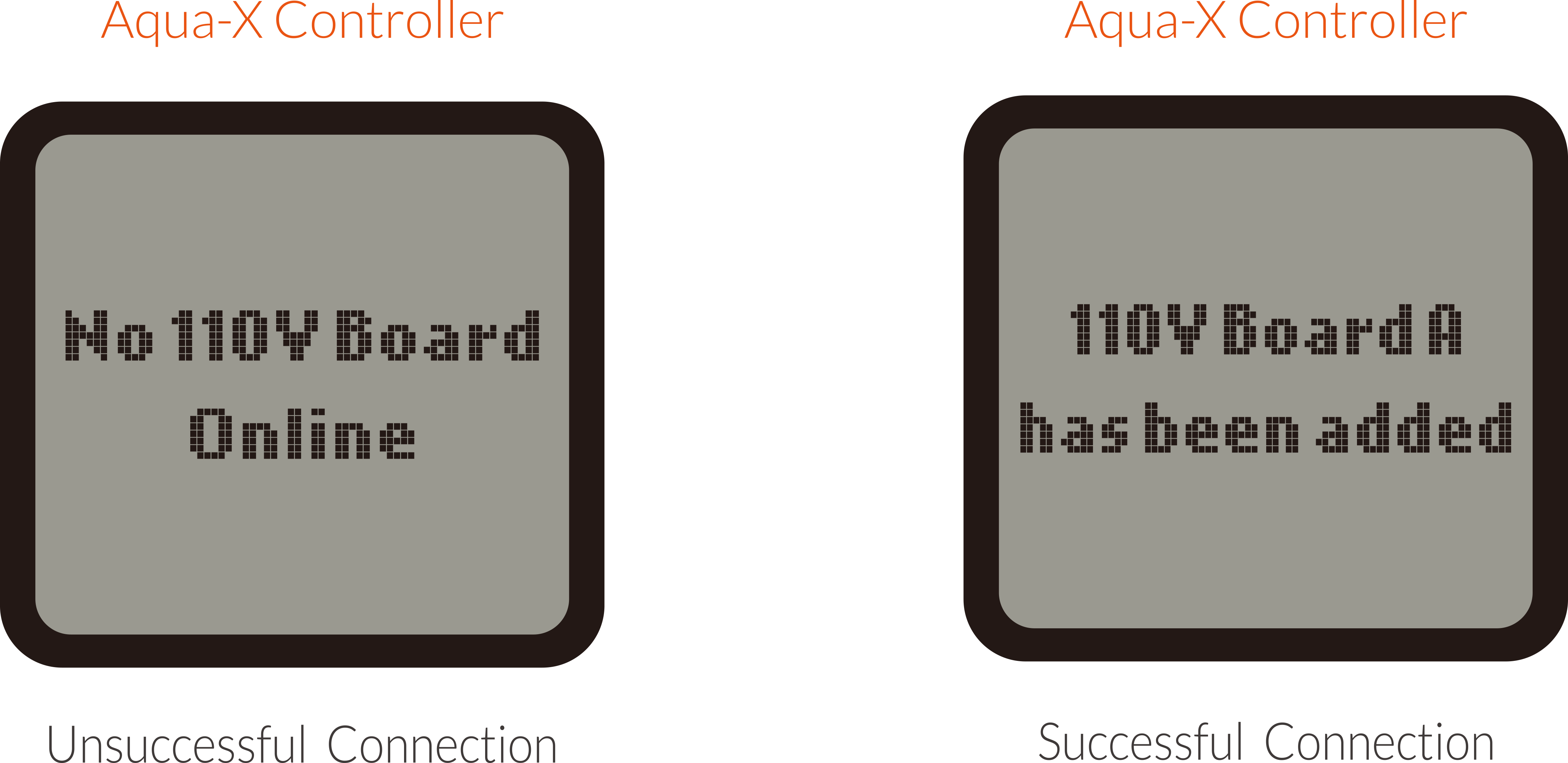
When the RJ12 cable is not correctly connected to the specific 110V CONTROL port or the 110V
Control Board is not connected to the power supply or the 110V Control Board has not yet been assigned to the
Aqua-X Controller, the LCD screen of the Aqua-X Controller will show “No 110V Board Online” on the setting page.
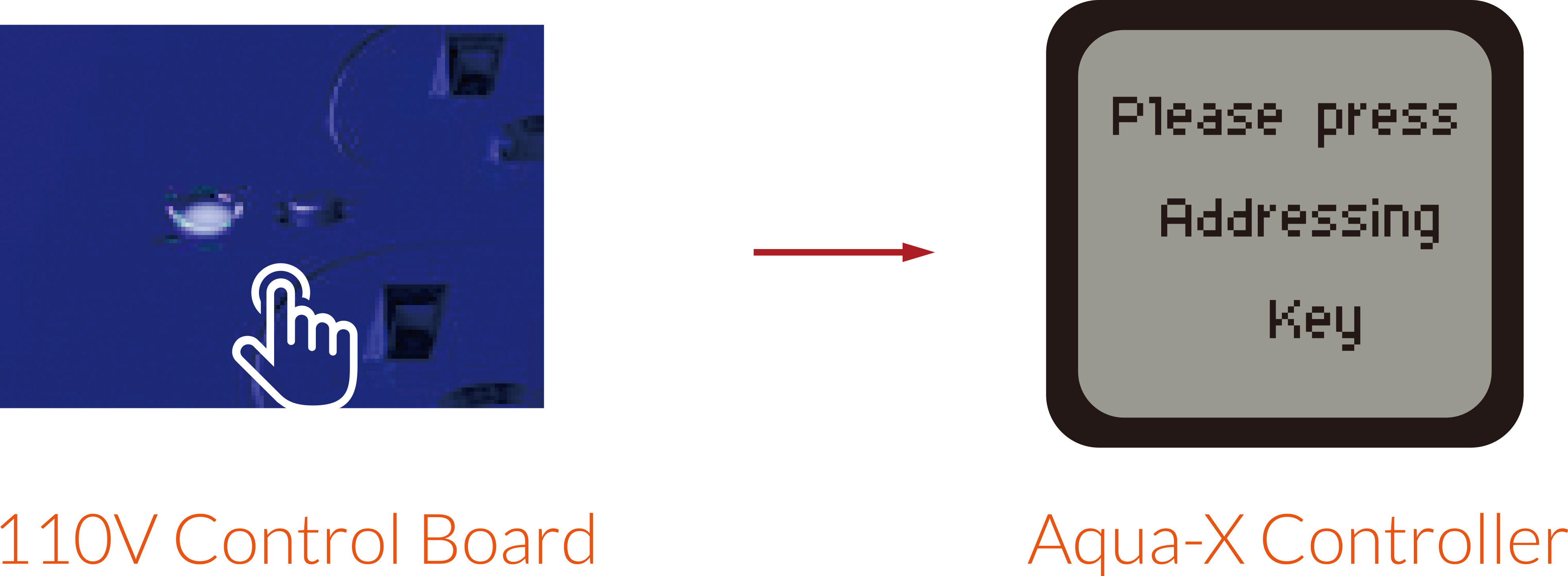
Please make sure the RJ12 cable is correctly connected and power on the 110V Control Board. After power-on, the LED
power indicator will keep flashing every second. Then press the ADDRESSING button on the 110V Control Board, the
LCD screen of the Aqua-X Controller will display “110V Board A has been added”. The first connected Control Board
will be marked as “A”, and the second one marked as “B”, the third one as “C”, and so on.
3. 110V Control Board Setting
On the SETTING page, press the ENTER button to enter the 110V Control Board list page. The connected Control
Board(s) will be shown page to page. User can press RIGHT button to select the 110V Control Board (A, B, C…) for
the setting change.
When the Control Board is selected, press ENTER button and the 1st output will be highlighted and blinking. Press
LEFT, RIGHT, UP or DOWN button to select the output such as 110V A1. Press ENTER button to confirm and enter the
SETTING page of that output.
On the SETTING page of selected output such as 110V A1, press ENTER button and the tick icon on
the “By schedule” will be highlighted and blinking. You can also press DOWN button to select “By recycle”. Press
the ENTER button to confirm and save the setting.
a) By Schedule:
Once the "By schedule" setting is selected, user can press ENTER button to activate the setting
for the 1 line of total 12 lines of schedule.The Hour of "On at" time will be highlighted and blinking, which means
that it's ready for change. User can press UP or DOWN button to change the HOUR. Press ENTER button and the MINUTE
of "On at" will be highlighted and blinking, user press UP or DOWN button to change the minute. Press ENTER button
and the SECOND will be highlighted and blinking, user can press UP or DOWN button to change the second. Press ENTER
button and the tick symbol will be highlighted and blinking. Finally, press ENTER button to confirm and save the
changes and the LCD screen will display "Setting saved".
Similarly, user can change the "On at" & "Time" for other schedule ( up to 12 lines) as above processes.
b. By recycle
Once the "By recycle" setting is selected, user can press UP or DOWN button to select " Start",
"On time", "Off time" & "Times" for change. Press ENTER button to activate the setting. For example, when "Start"
selected, press "ENTER" button and the HOUR will be highlighted and blinking, user can press UP or DOWN button to
change the hour. Press ENTER button and the MINUTE will be highlighted and blinking, press UP or DOWN button to
change the minute. Finally, press ENTER button to confirm and save the change and the LCD screen will display "
Setting saved"
Similarly, user can change the "On time", " Off time" and "Times" accordingly.
4. SPECIFICATIONS

5. GENERAL INFORMATION
a). Please use TrolMaster’s components for better performance
b). In the case of defects of the Control Board, the Control Board will either be replaced or
required using new
or reconditioned products or parts by TrolMaster within three-year warranty from the original date of purchase. For
service, return the Control Board in good packaging to our agent with the original sale receipt.
c). Non-professionals DO NOT open the cabinet to prevent electric shock or damage to the Control
Board.
 WARNING : DO NOT allow the Control Board to be exposed to
water or excessive heat. DO NOT open or attempt to
repair or disassemble the Control Board, as there are no user-serviceable parts inside. Opening the controller will
void the warranty.
WARNING : DO NOT allow the Control Board to be exposed to
water or excessive heat. DO NOT open or attempt to
repair or disassemble the Control Board, as there are no user-serviceable parts inside. Opening the controller will
void the warranty.
1. If the surface of Control Board is dirty, wipe it with a dry towel.
2. The Control Board is designed for indoor use only, it should be operated under natural ventilation conditions.
3. For safety, it is necessary to connect the ground wire. If a short circuit did occur, the current would
flow through the ground wire, causing a blown fuse or tripped circuit breaker.
4. The Control Board should be positioned in a place that it’s easily to be pull out when a fault occurs.