Overview
Thank you for purchasing TrolMaster’s TS-2 Thermostat Station for use with the Hydro-X master controller. It is
specifically designed to replace the traditional thermostat to control four different system ( Heat/Cool, Cool
only, Heat only, Heat pump) for the purpose of constant temperature auto control.
Mount the TS-2 near the thermostat device using the pre-existing control wires, now you can use the TS-2 in
conjunction with the Hydro-X to control your thermostat devices easily. Choose your desired temperature setpoints
for the Day / Night mode (see Temperature Settings in Hydro-X’s instructions), the TS-2 will turn on/off Cooling
Mode or Heating Mode automatically based on the setpoint.
There is no need to provide power supply for the TS-2 unit. It can be connected to the Hydro-X with a simple RJ12
phone cable. After power-on, the Hydro-X will send the controlling data to the TS-2 automatically. The LCD screen
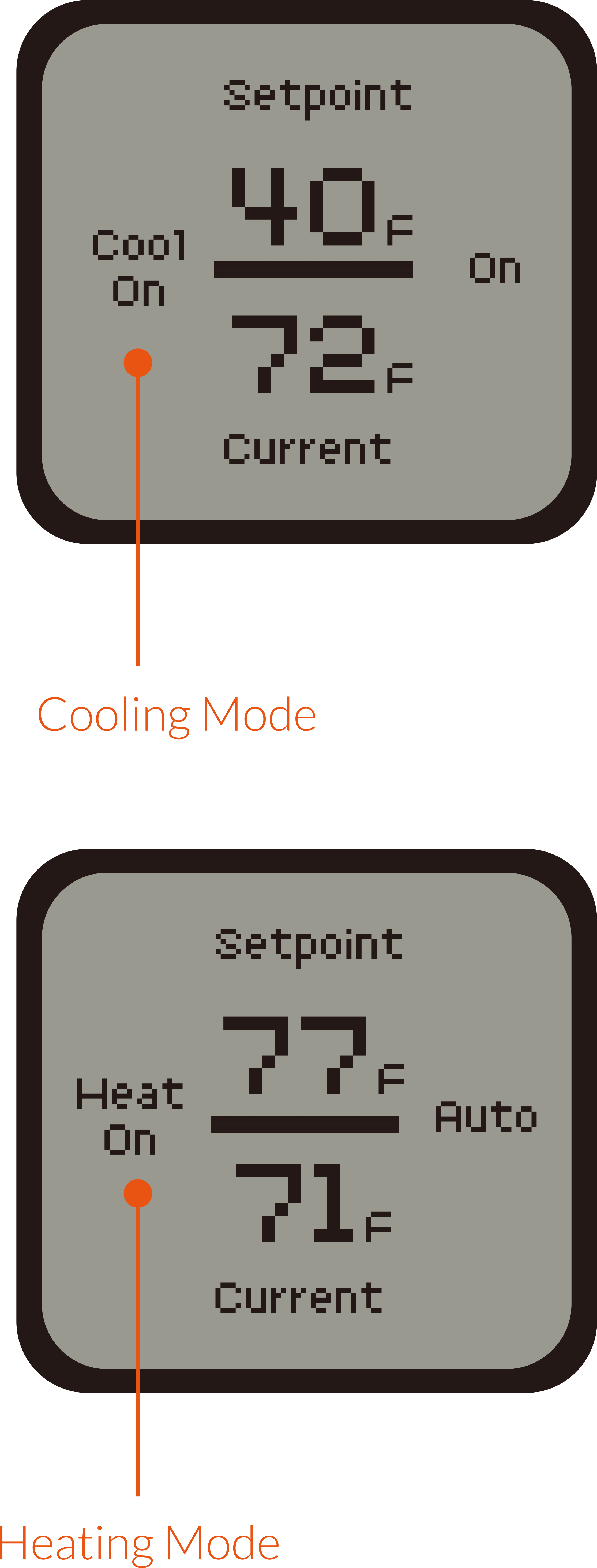
of the TS-2 will display the setpoint (upper part) and current temperature (lower part). When the current measured
temperature is beyond the setpoints, the TS-2 unit will control the thermostat device to perform cooling mode (Cool
On) or heating mode (Heat On) automatically.
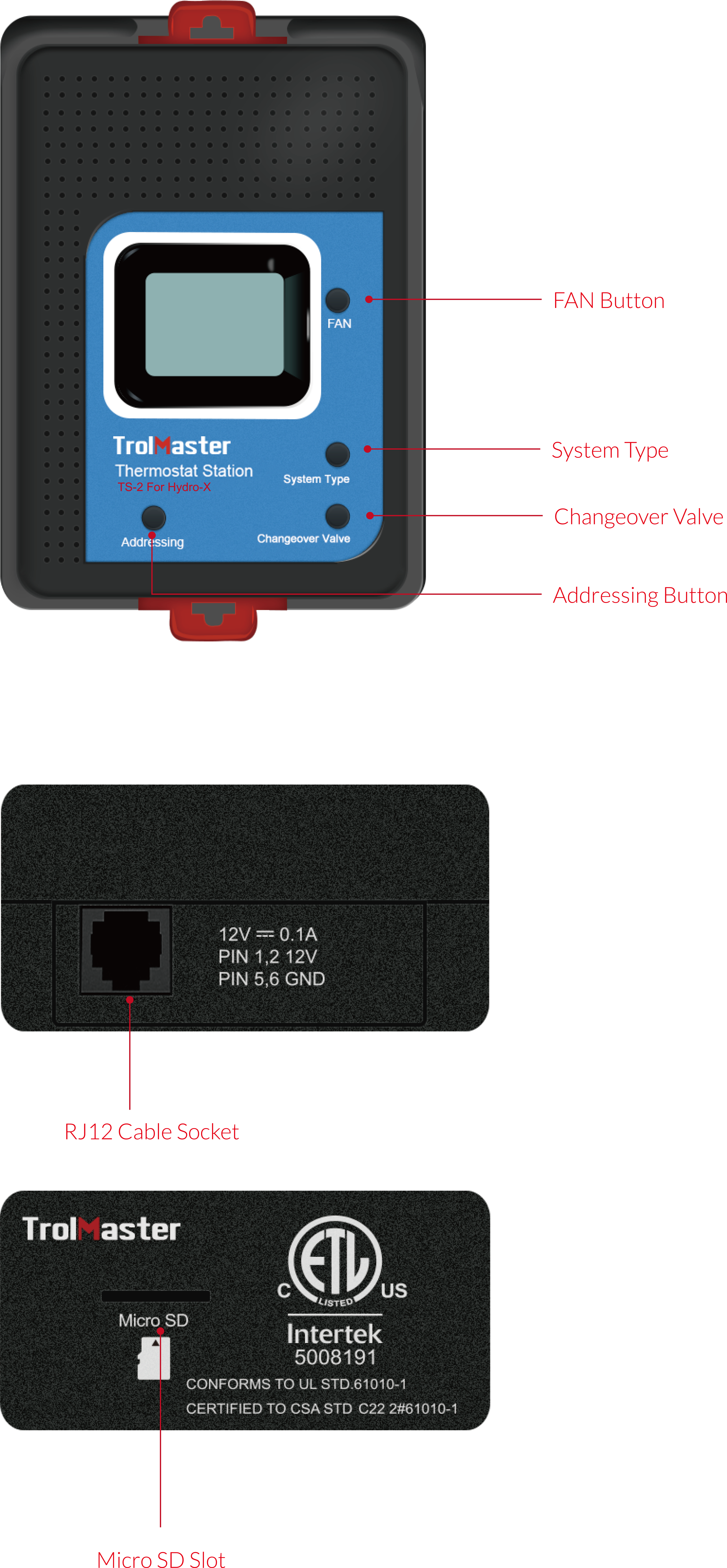
Features
Installation
Pull the 2 tabs outward to release the bracket from the unit, mount the bracket to wall or surface near the
thermostat cable, which consists of 5 or 6 color signal wires. Peel off the outer sheath of all wires to reveal the
copper wire.
Then, insert each bare wire into Heat Pump Terminals (R, O/B, Y, G, AUX/E) or Conventional Terminals ( R, W, Y, G,
W2, Y2) on the back panel while pressing the button of the terminal designation at the same time.
Release the button to clamp the wire in each terminal. Verify wire is firmly secured by gently pulling on wire.
Finally, place the unit back on the bracket and press the 2 tabs back in to lock the unit in place.
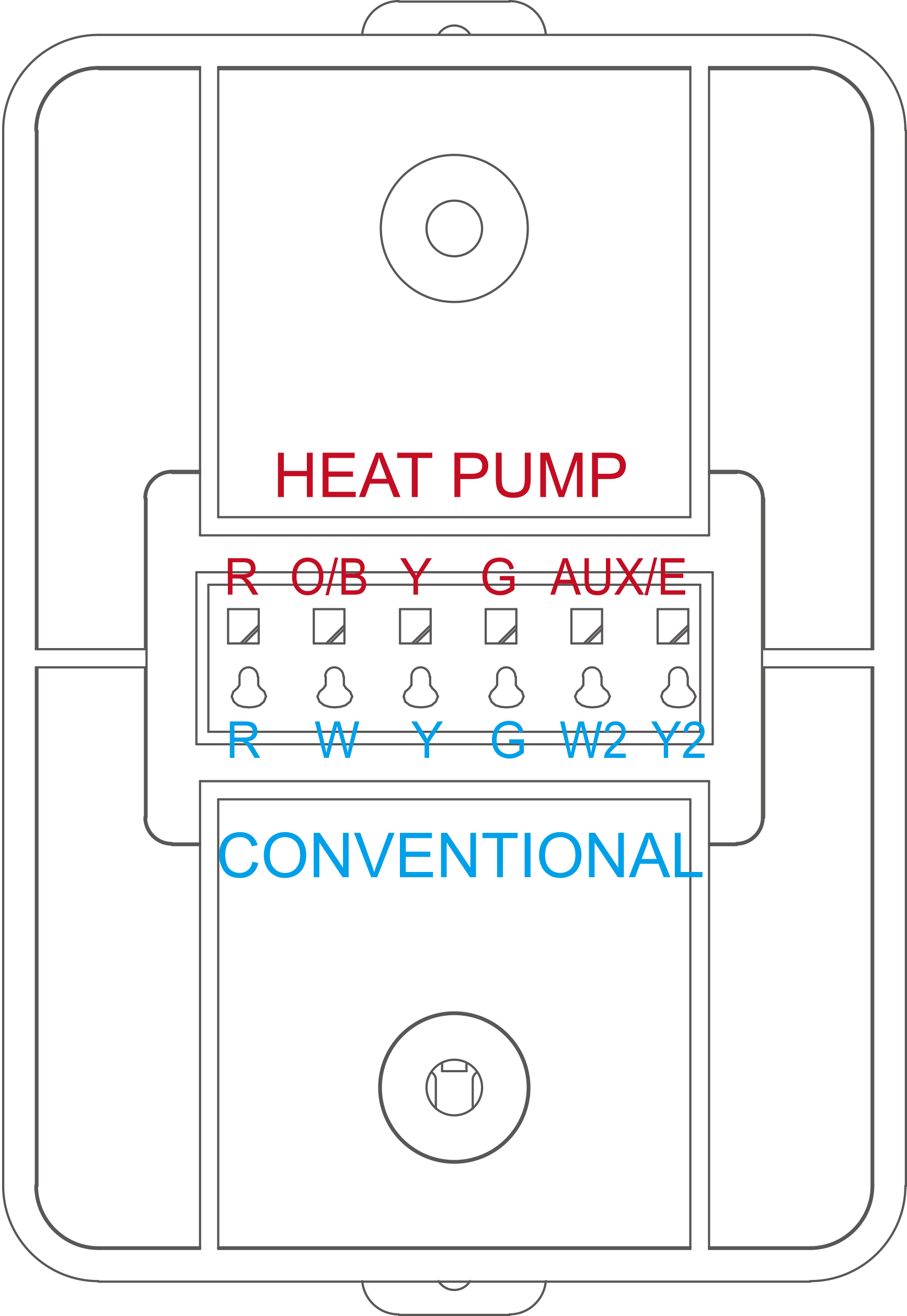
Wiring terminal designation
Heat Pump Terminals
R
O/B
Y
G
AUX/E
24VAC power from heating transformer
Changeover valve
Compressor contactor
Fan relay
Auxiliary/Emergency heat relay
Conventional Terminals
R
W
Y
G
W2
Y2
24VAC power from heating transformer
Heat rely (stage 1)
Compressor contactor (stage 1)
Fan relay
Heat relay (stage 2)
Compressor contactor (stage 2)
Operation Instructions
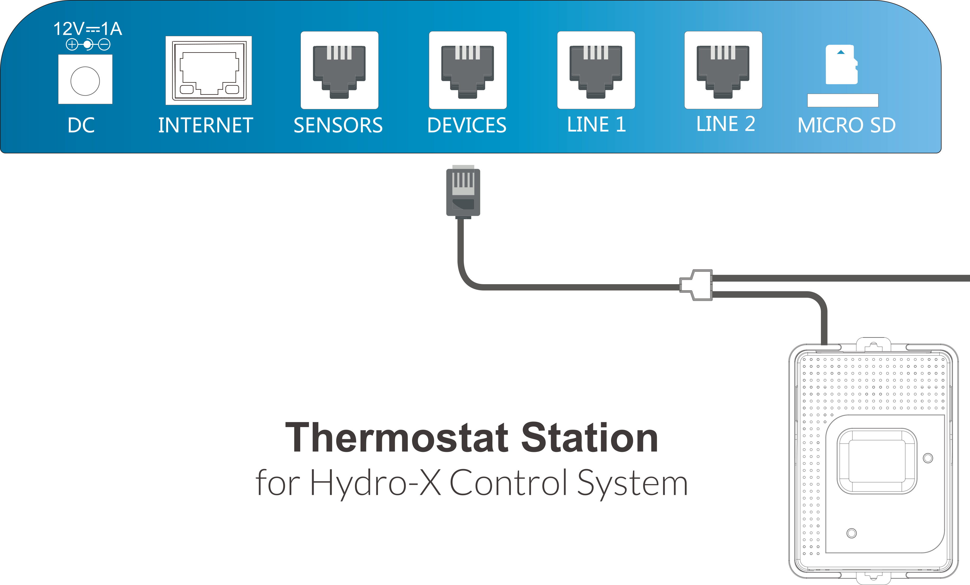
1. Connection to Hydro-X
After the signal wires are successfully connected to the TS-1 unit, connect the TS-1 to the Hydro-X with a RJ12
cable through the DEVICES port on the bottom of Hydro-X. See below connection diagram for reference.
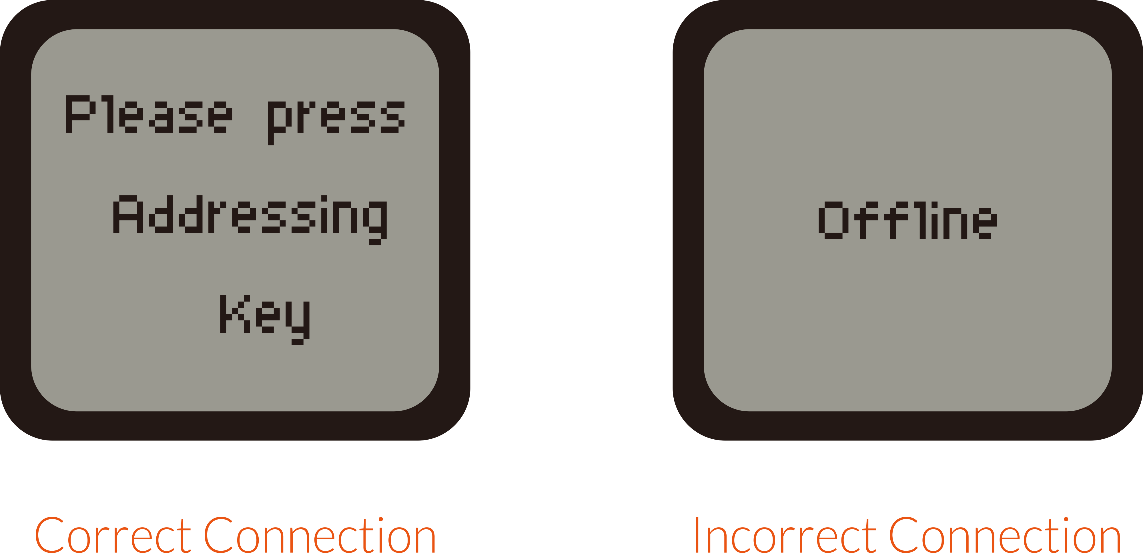
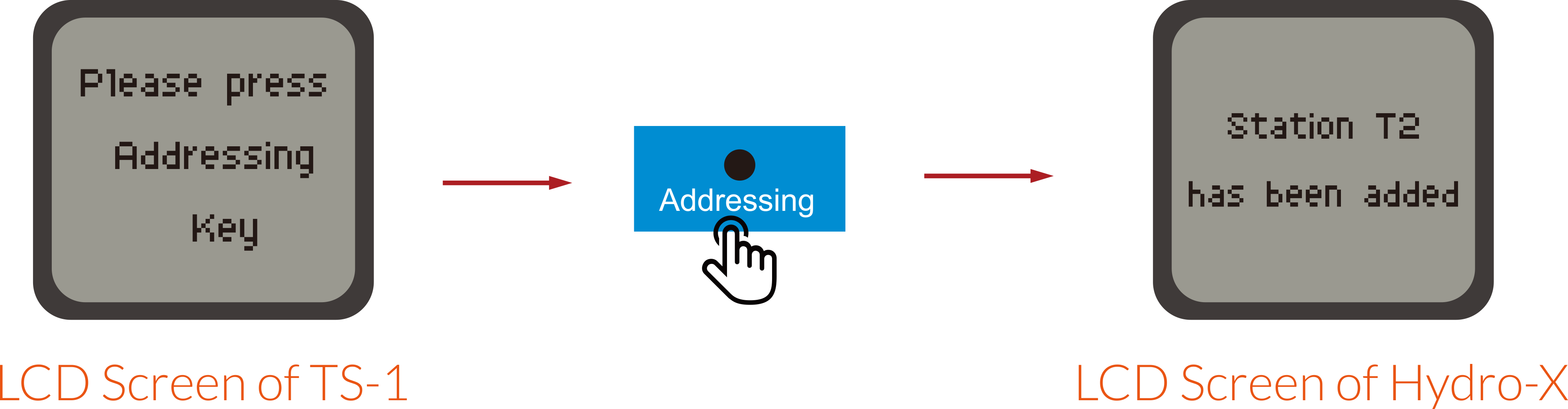
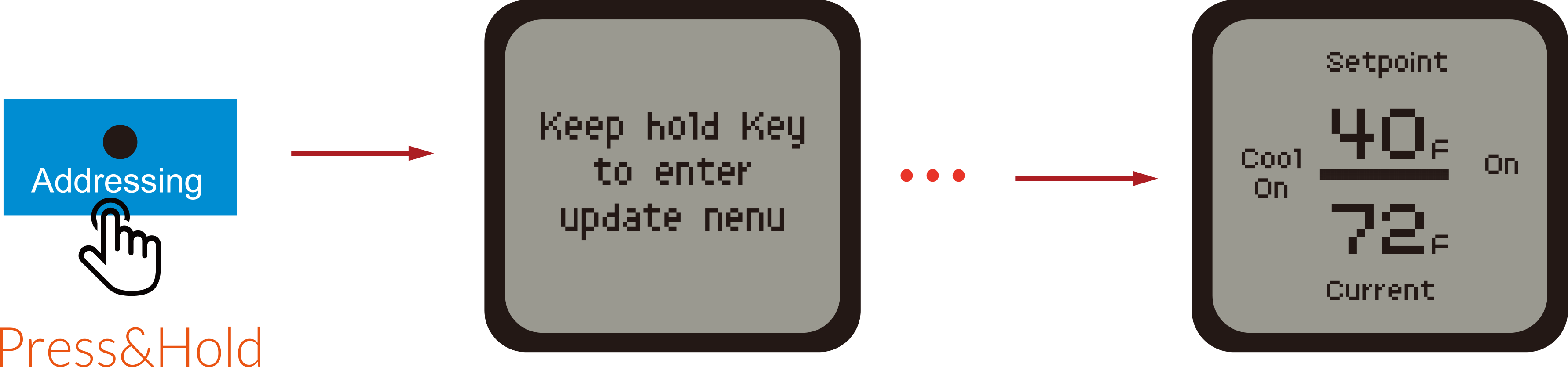
After power-on, the LCD screen of TS-2 will show “Please press Addressing Key” when TS-2 is connected correctly.
Otherwise, it will show “Offline” when the TS -2 is connected incorrectly.
2. Address Assignment
Press the Addressing button on the TS-2 unit so that the Hydro-X will assign an address such as T2 to the TS-2 unit
accordingly. The LCD screen of Hydro-X will display “Station T2 has been added”. T2 is not the constant product
code, it can be T1, T3, T4… depending on the connection sequence of the temperature devices. The first one is
marked as T1, the second one as T2, and so on.
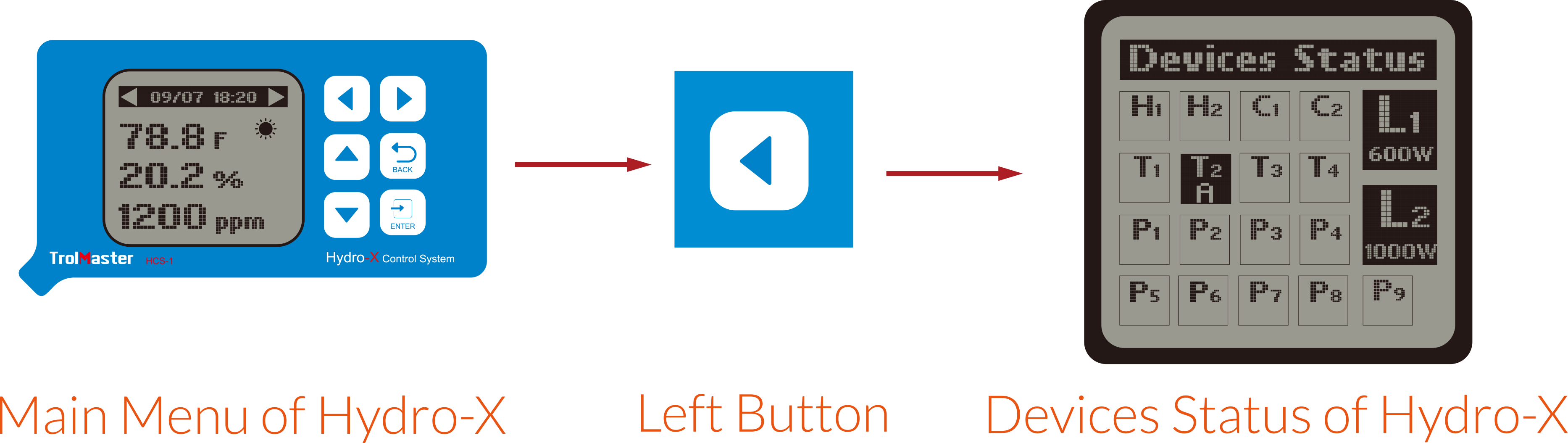
You can also check the address code on the Hydro-X as shown below:
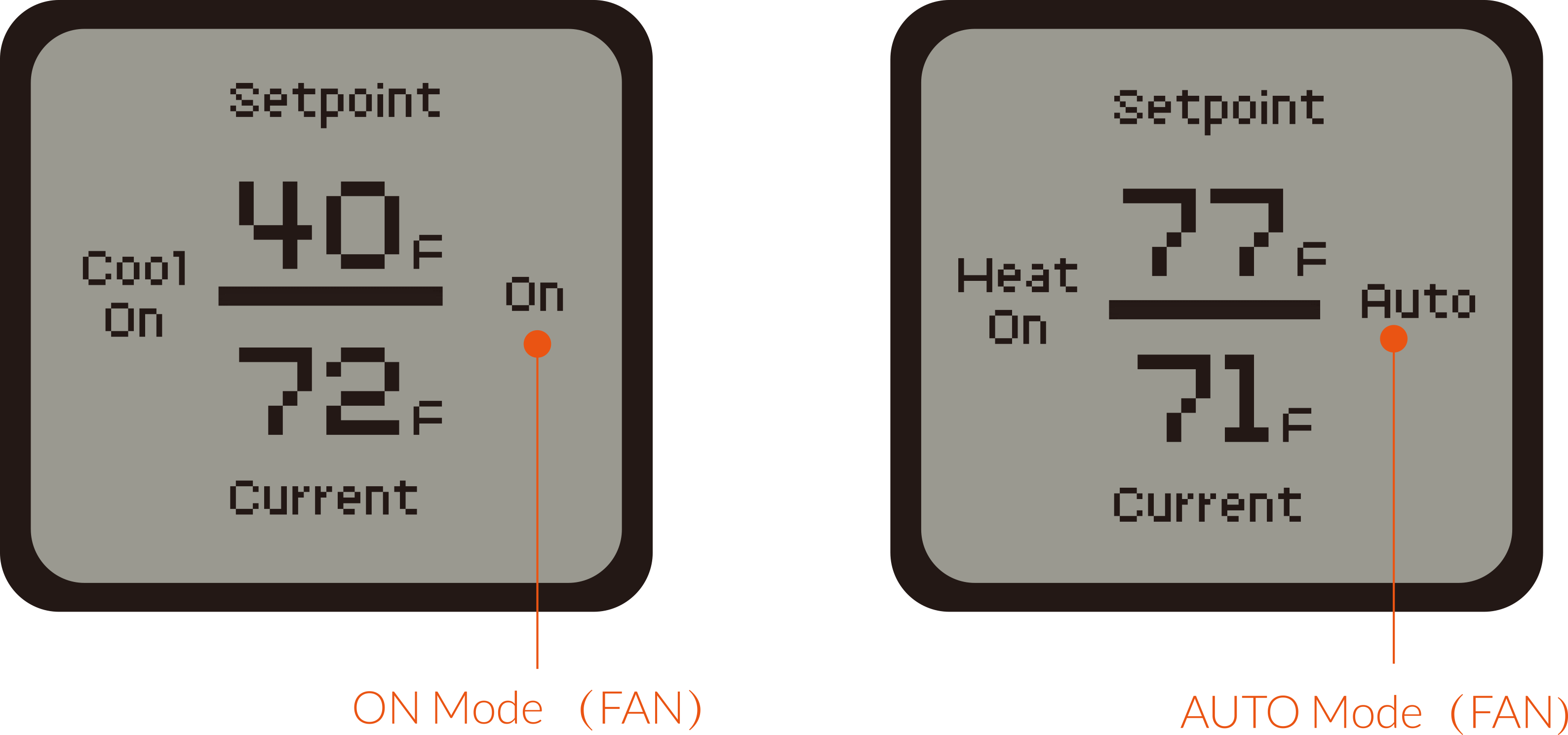
3. FAN Setting
Press FAN button to switch between ON mode and AUTO mode for the fan inside an air-conditioner.
AUTO : Fan runs only when the heating or cooling system is on. Auto is the most
commonly used setting.
ON : Fan is always on.
NOTE : Options may vary depending on your heating/cooling equipment.
NOTE:
1. When one of the four system types is selected, press and hold the “System Type” button
for 3 seconds and the LCD screen of TS-2 will return back to main menu.
2. When the FAN is set into Auto mode, FAN will continue to work for 1 minute before stop when Heat or Cool is
stopped.
4. Select System Type
After power-on, the LCD screen of TS-2 unit will display the setting temperature (setpoint) and current
temperature. Press and hold the “System Type” button for 3 seconds on the main menu, the LCD screen of TS-2 will
display in 4 modes in sequence: Heat/Cool, Cool only, Heat only, Heat pump as illustrated below.
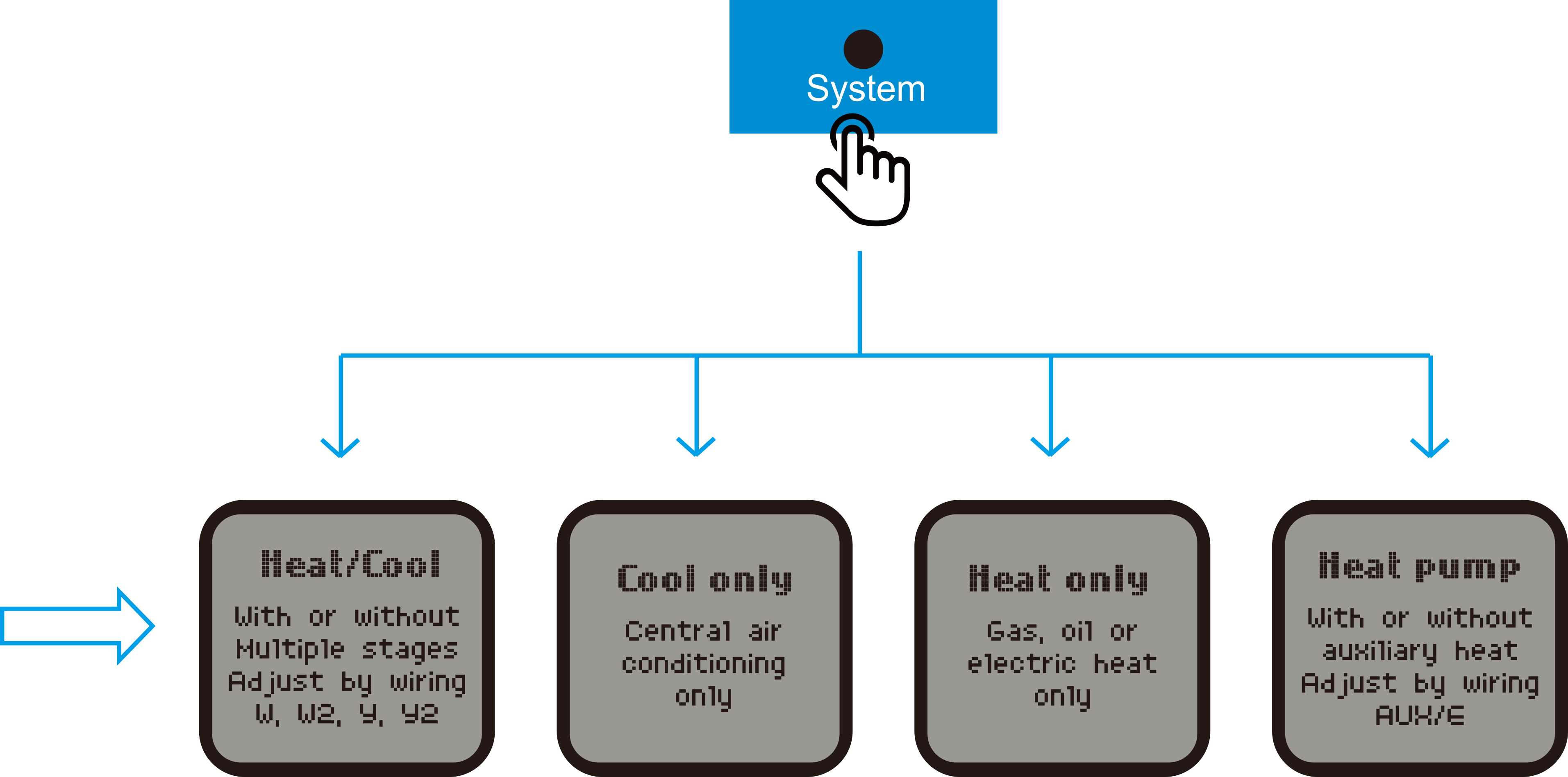
Heat/Cool : Heat/cool device that can be used for heating or cooling. With or
without multiple stages by wiring W,
W2, Y, Y2, W (stage 1) and W2 (stage 2) for heat control wire. Y(stage 1) and Y2 (stage 2) for cool control wire.
Cool only : Control air conditioner only.
Heat Only : Control gas heater, oil heater or electric heater only.
Heat Pump : Control heat pump. With or without auxiliary heater by wiring
terminal
AUX/E.
The TS-2 will turn on Cooling Mode or Heating Mode automatically depending on the variance between current
temperature and setpoint. For example, when the current temperature is HIGHER than the setpoint, the TS-2 will
start cooling mode and display “Cool On” on the screen. When the current temperature is LOWER than the setpoint,
the TS-2 will start heating mode and display “Heat On” on the screen.
NOTE : When one of the four system types is selected, press and hold the
“System
Type” button for 3 seconds and the LCD screen of TS-2 will return to main menu. Or wait for a 1 minute timeout to
automatically return to the main interface
5. Changeover Valve
When the Heat Pump mode is selected, press and hold the “Changeover Valve” button for 3 seconds, the LCD screen of
TS-2 will display Heating and Cooling mode in sequence.
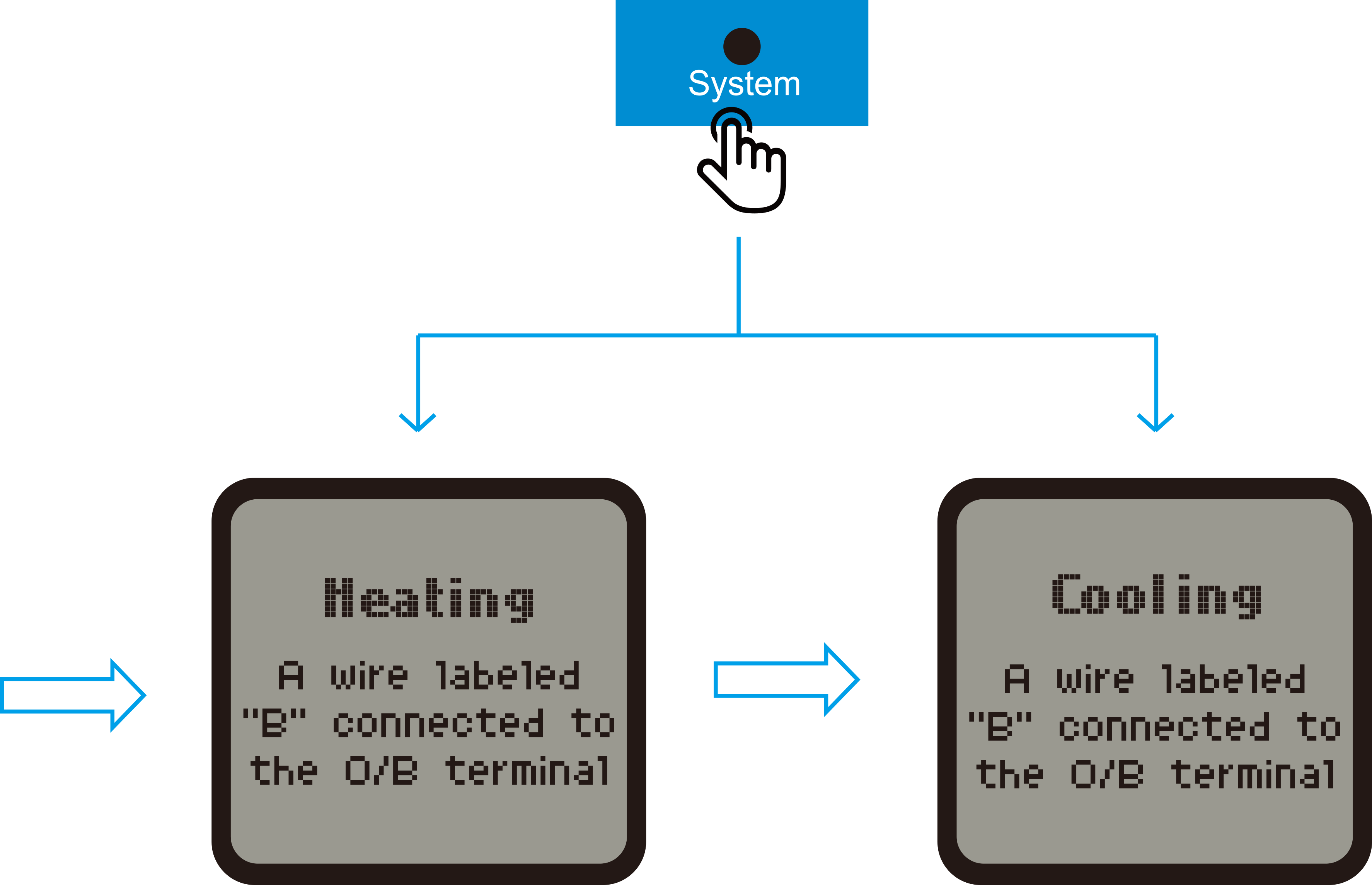
Heating changeover valve: Use this setting if you have connected a wire labelled
“B” to the O/B terminal.
Cooling changeover valve: Use this setting if you have connected a wire labelled
“O” to the O/B terminal.
NOTE :
1. When the device type is Heat Pump, the time interval for restart must be 5 minutes after stopping the Heating
mode or Cooling mode. If less than 5 minutes, the output will not be opened and the LCD screen displays “Heart On”
or “Cool On” and blinks.
2. When the device type is Heat/Cool or Cool only, the time interval for restart must be 5 minutes after
stopping the Cooling mode. If less than 5 minutes, the output will not be opened and the LCD screen displays “Cool
On” and blinks.
6. Firmware Upgrade
Press and hold the “Addressing” button while replugging the RJ12 cable, the upgrade process will be done
automatically.
*NOTE: Make sure the file name of firmware upgrade should be named as “
ts2_update.tex”.
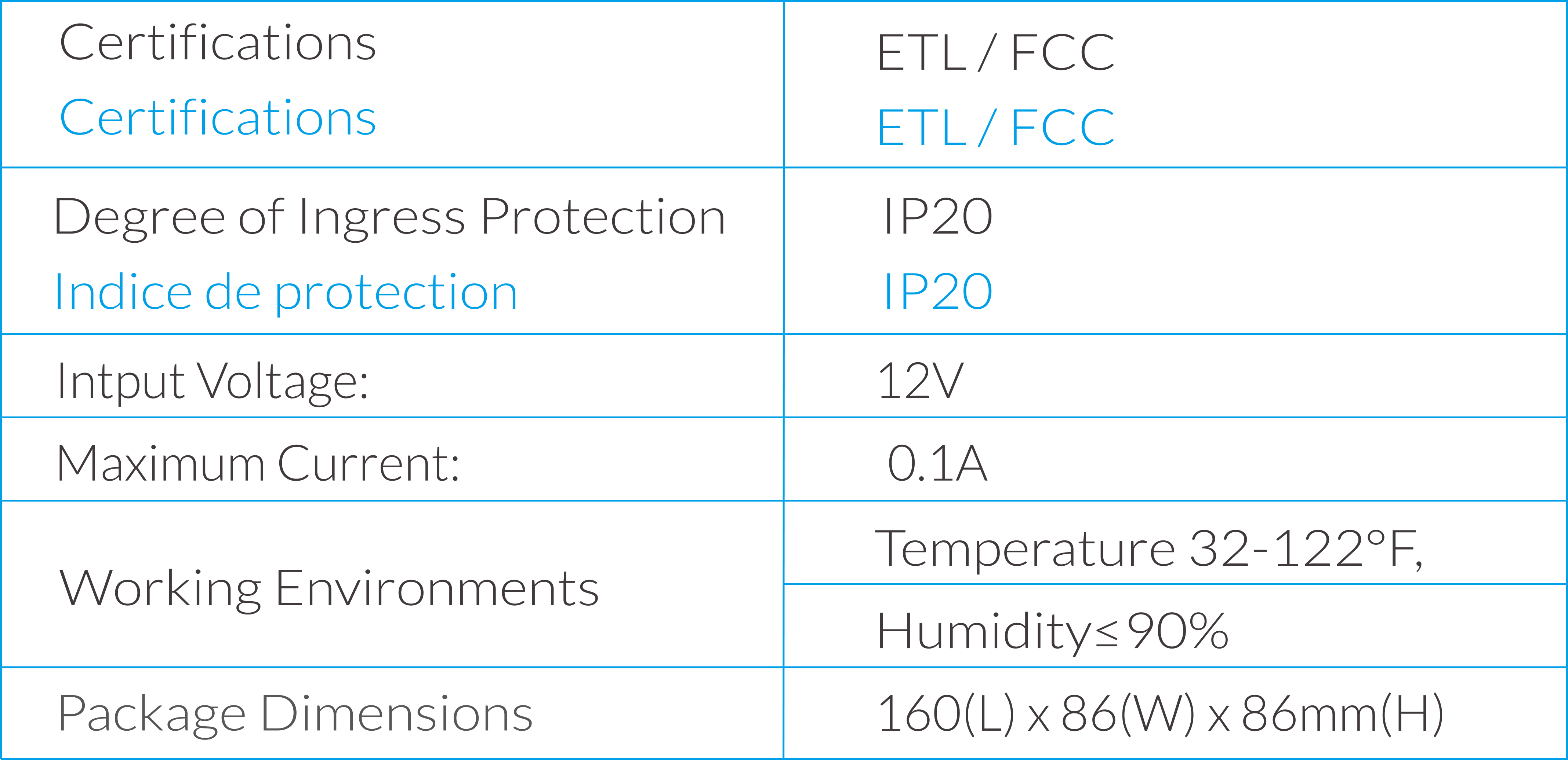
7. Specifications
8. GENERAL INFORMATION
a ) Please use TrolMaster’s components for better performance.
b ) In the case of defects of the Thermostat Station, the Thermostat Station will either be replaced or repaired
using new or reconditioned products or parts by TrolMaster within three-year warranty from the original date of
purchase. For service, return the Thermostat Station in good packaging to our agent with the original sale receipt.
c ) Non-professionals DO NOT open the cabinet to prevent electric shock or damage to the Thermostat Station.
 WARNING : DO NOT allow the Thermostat Station to be exposed
to
water or excessive
heat. DO NOT open or attempt to repair or disassemble the Thermostat Station, as there are no user-serviceable
parts inside. Opening the controller will void the warranty.
1 . If the surface of Thermostat Station is dirty, wipe it with a dry towel.
2 . The Thermostat Station is designed for indoor use only, it should be operated under natural ventilation
conditions
3 . For safety, it's necessary to connect the ground wrie. If a short circuit did occur, the current would flow
through
the ground wire, causing a blown fuse or trippde circuit breaker.
4 . The Thermostat Station should be positioned in a place that it’s easily to be pulled out when a fault occurs.
WARNING : DO NOT allow the Thermostat Station to be exposed
to
water or excessive
heat. DO NOT open or attempt to repair or disassemble the Thermostat Station, as there are no user-serviceable
parts inside. Opening the controller will void the warranty.
1 . If the surface of Thermostat Station is dirty, wipe it with a dry towel.
2 . The Thermostat Station is designed for indoor use only, it should be operated under natural ventilation
conditions
3 . For safety, it's necessary to connect the ground wrie. If a short circuit did occur, the current would flow
through
the ground wire, causing a blown fuse or trippde circuit breaker.
4 . The Thermostat Station should be positioned in a place that it’s easily to be pulled out when a fault occurs.